Install a Motherboard With a Fixed Rear I/O Shield and Tight Case Tolerances
I’ll clarify how to fit a motherboard with a fixed rear I/O shield into a case that leaves little room for error, including when to change your installation approach instead of forcing the board or its connectors.
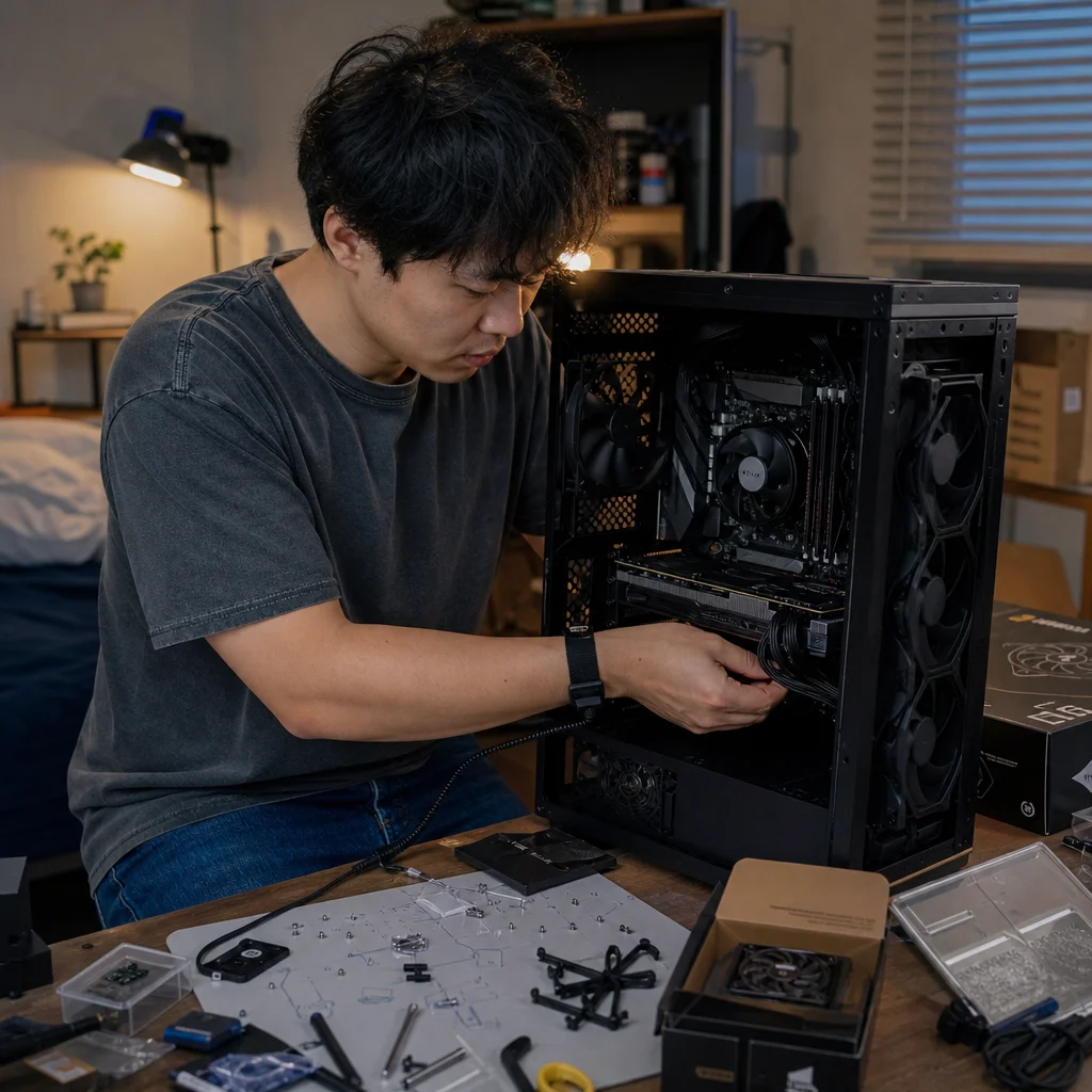
A motherboard with a fixed rear I/O shield can make installation feel backwards. You need to line up the shield openings with the case, the mounting holes with the standoffs, and the expansion slots with the rear brackets—often while the case gives you almost no room to adjust the board. The right approach is controlled alignment, not pressure.
The main trade-off is between installing the board straight down and inserting it at a shallow angle. A straight drop is simple when the case has generous clearance. In a tight case, a slight angle can help the fixed shield pass through the rear opening before the motherboard settles onto the standoffs. That method gives you more control, but it also makes it easier to catch a shield spring tab or misplace the board on a standoff. Understanding when to use each approach prevents most problems.
Prepare the case before bringing in the motherboard
Remove the side panels and lay the case on its side so the motherboard tray faces upward. This gives you gravity-assisted support instead of asking you to hold the board in midair while you search for mounting holes. If the case has a removable motherboard tray, removing it can be the best solution for tight tolerances, even if it adds a few extra steps.
Take out anything that blocks the board’s travel path. A front fan, top radiator, large CPU cooler, or cable bundle can turn a manageable alignment problem into a cramped one. You don’t necessarily need to remove every nearby component, but you should be able to see the rear opening, the standoffs, and the expansion-slot area at the same time.
Check the motherboard tray before installation. The standoffs should match the motherboard’s size and mounting-hole pattern, and no extra standoff should sit beneath a place where the board has no mounting hole. An incorrectly placed standoff can press against the underside of the motherboard and cause damage when you tighten the screws. Some cases use fixed or raised mounting points, so compare the tray with the board rather than assuming every visible point is needed.
Also inspect the rear opening. The fixed I/O shield is already attached to the motherboard, so the case must have enough clearance for the shield housing to enter the rectangular opening. Look for a removable rear I/O plate, a bent section of case metal, or a cable that could catch on the shield as you lower the board.
Confirm the fit before committing: Check the motherboard’s form factor, the case’s supported board sizes, and the location of every required standoff in their current manuals. If the shield, mounting holes, or expansion slots can't align without force, stop and identify the obstruction instead of tightening screws to pull the parts into place.
Understand the fixed shield’s pressure points
A fixed rear I/O shield is usually more rigid than a loose snap-in shield. It may have spring-like tabs around the port openings, and those tabs are meant to make contact with the metal shield area around the connectors. They can catch on the case opening if you approach from the wrong direction.
Before installation, look at the shield from the rear and identify the parts that extend beyond the connector openings. Compare their position with the case’s I/O cutout. The goal is for the shield’s outer frame to pass through the opening while the connector faces remain centered in their individual apertures. If a tab is obviously folded into a port opening, correct the issue only as far as the board or its documentation permits; don’t use the connectors themselves as a lever.
The shield shouldn't need to be hammered, sharply bent, or forced through an opening that is visibly too small. Light spring pressure as the board moves into position is normal. Sudden resistance, scraping that stops the board, or a connector being pushed sideways is a reason to lift the board away and inspect it.
Choose the insertion path that suits the case
For a case with reasonable clearance, place the motherboard into the case with the rear I/O shield aimed toward the opening. Lower the board gradually while keeping the shield parallel to the opening. Once the shield has entered, shift the board slightly until the mounting holes sit over the standoffs. Keep a hand under the board’s unsupported edge so its weight doesn’t make the shield scrape downward.
A straight-down approach is usually the least complicated because the board’s holes remain easier to see and the standoffs are less likely to snag the underside. It works particularly well when the case has a wide top opening and the rear I/O cutout doesn't have a narrow lip that blocks the board’s movement.
A shallow-angle approach is often better when the case’s top edge or rear lip restricts vertical clearance. Start with the rear I/O shield slightly lower than the opposite edge of the motherboard. Guide the shield into the case opening first, then rotate the board down over the standoffs. The rotation should be smooth and deliberate; it isn't a way to wedge the shield through a smaller opening.
The trade-off is visibility. With the angled method, the rear edge may align before you can see the mounting holes. Keep the board supported and lower it only after you know the shield has cleared the opening. If you lose track of the standoffs, lift the board back out rather than sliding it around on the tray.
In either method, don’t use a motherboard screw to pull a misaligned board into place. A screw can appear to solve a small alignment error while bending the board or leaving another hole unsupported. The screw should pass through the motherboard hole and enter the standoff naturally, with only modest turning resistance.
Align the rear I/O shield, standoffs, and slots together
There are three alignments to check before fastening anything. First, the rear connectors should sit in the centers of their shield openings, with no port face trapped under a shield edge. Second, the motherboard mounting holes should be directly above the standoffs. Third, the expansion-slot edges should line up with the case’s rear slot openings.
These alignments affect one another. If the board is too far toward the front of the case, the I/O connectors may not sit correctly and the expansion slots can shift away from their brackets. If it is too far toward the rear, the shield may press against the case opening while the front mounting holes miss their standoffs. Make small adjustments while the board is still loose, checking all three areas after each change.
The expansion-slot area deserves particular attention. The motherboard’s rear edge should sit behind the case’s slot covers, while the metal brackets on the graphics card or other expansion cards will later line up with those openings. If the board is resting against a case lip or a mispositioned standoff, the slots may look close but remain impossible to use cleanly.
Once the board is seated, install one screw near the center or another point that holds the board without pulling it sideways. Don't fully tighten it immediately. Confirm the rear shield and slot alignment again, then install the remaining screws. Tighten them in stages until snug. The purpose is to hold the motherboard securely, not to compress it against the tray.
Diagnose resistance instead of increasing force
If the board stops partway in, first determine where it stops. Resistance at the rear opening often points to a shield tab, a case lip, or insufficient clearance. Resistance underneath the board suggests a misplaced standoff or a tray feature contacting the underside. Resistance at the expansion slots can indicate that the board is shifted forward or that the rear bracket area isn't compatible with the case.
Remove the board and inspect for marks rather than guessing. A fresh scrape on the shield frame, a bent spring tab, or a shiny contact point on the tray can reveal the obstruction. Check that no loose screw has fallen beneath the board and that cables aren't trapped between the motherboard and tray.
If the motherboard fits only when its connectors are pushed sideways, the case and board may have unusually tight tolerances—or may not be a good combination. A different insertion angle, a removable tray, or temporarily removing an obstructing fan can solve a genuine clearance issue. Filing or bending the case shouldn't be the first response, and it can create sharp edges or weaken the mounting area.
Some cases have adjustable or removable standoffs, while others use fixed mounting points. If the board’s holes consistently miss the standoffs by a noticeable amount, verify the case’s supported form factor and mounting pattern. A compatible board shouldn't require the motherboard to be held under continuous tension to make the holes line up.
Finish the installation without trapping cables
Before tightening the final screws, route only the cables that will become difficult to access once the motherboard is installed. The CPU power cable is a common example: in a tight case, it may be easier to route it through the upper cutout before the board blocks part of that path. Don't place a cable beneath the motherboard or between the board and tray.
Keep front-panel, USB, fan, and audio cables out of the rear I/O opening while you lower the board. A cable caught behind the shield can prevent the motherboard from sitting flat, and the obstruction may not be visible once the board is partly installed. Pre-routing helps, but leave enough slack that the cables don't pull the motherboard toward an edge.
After the screws are snug, look across the board and tray for bowing. Check that no connector is being pressed against the case, that the rear I/O ports remain centered, and that the expansion-slot covers still line up. Install the rear slot covers or expansion cards only after this basic alignment looks correct.
Installing a fixed-shield motherboard in a tight case is mainly an exercise in choosing the least awkward path. Use a straight drop when you have visibility and clearance; use a shallow angle when the case’s upper or rear structure demands it. In both cases, let the shield enter first, keep the board supported, and treat unexplained resistance as information.
Once the board sits flat and all three alignments—rear ports, standoffs, and expansion slots—look correct, fastening it should be uneventful. If it isn’t, back up and find the cause. A few minutes spent changing the approach or removing an obstruction is safer and usually faster than forcing a connector, bending the shield, or using screws to correct a fit that was never aligned.