How to Handle a Build When the Motherboard Is Already Installed in the Case
Common difficulty: a case-installed motherboard turns simple upgrades into awkward work around heatsinks, cables, and tight clearances. I’ll show you a careful installation order that reduces damage, avoids unnecessary disassembly, and helps recover a refurbished or partially assembled PC with confidence.
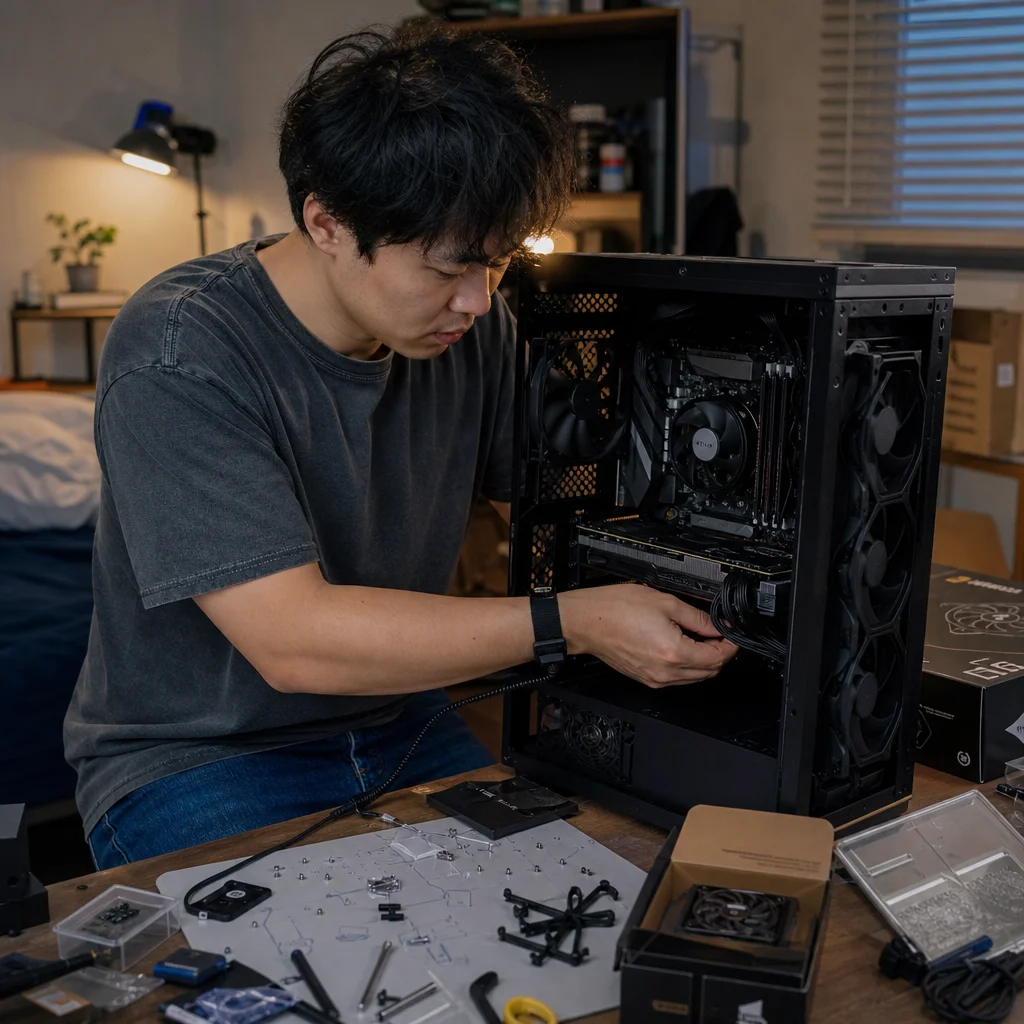
Working on a motherboard after it’s already mounted in the case is rarely impossible, but it can make every step less forgiving. Memory slots may sit beneath a cooler, an M.2 socket may be hidden by a graphics card, and the power connectors may be difficult to reach once drives and fans are in place.
The safest approach is to treat the existing system as something you’re recovering, not as an empty case you can assemble in any order. Confirm what is already installed, create access where it matters, and add parts in an order that keeps later connections reachable.
Start with a controlled inspection
Shut the computer down normally if it is operational, then switch the power supply off and disconnect the power cord. Press the case’s power button for a few seconds after unplugging it to discharge some residual power. Place the case on a stable, well-lit surface, preferably with the side panel removed and the motherboard’s rear side supported by the case rather than by a loose work surface.
Before touching components, take a few photographs of the existing cable routing and connectors. Include the motherboard’s 24-pin power connector, the processor power connector near the top edge, front-panel headers, storage cables, fan headers, and any graphics-card power leads. These pictures give you a reference if you need to move several cables out of the way.
Look for obvious problems before adding anything: loose screws, bent cables pressing against fans, missing motherboard standoffs, damaged connectors, dust packed into heatsinks, and parts that appear to be unsupported. If the system is secondhand, don’t assume that every cable is connected correctly simply because the machine previously powered on. A photo is useful evidence of the starting state, not proof that the starting state is good.
Confirm your board’s layout: Before removing a graphics card, heatsink, or cover, check the motherboard and component manuals for the correct memory slots, storage sockets, fan headers, and connector locations. Board layouts differ, and forcing access based on appearance can damage a latch or connector.
Decide what needs to move
You don’t always need to remove parts just because they make access less convenient. Avoid unnecessary disassembly when the new component can be installed without force and when you can see the relevant slot clearly. Every removed component introduces another opportunity to damage a connector, disturb thermal paste, or reconnect a cable incorrectly.
On the other hand, awkward access is a good reason to remove a graphics card or a large cooler rather than work around it. If your hand would have to press against a fan blade, bend a memory module, or push a screwdriver toward the motherboard, stop and create more room. A few minutes of planned removal is cheaper than replacing a damaged board.
Remove the side panel opposite the motherboard as well if the case has one. That opening can expose cable slack, allow you to push a connector through a routing cutout, or provide access to the screws holding a drive cage. In some cases, the rear panel is the difference between routing a cable cleanly and forcing it across the motherboard.
If you remove a graphics card, disconnect its power cable first, release the rear bracket screws, and press the motherboard’s PCIe slot latch before lifting the card straight out. Hold the card by its edges and place it on a nonconductive surface. Don’t pull on the fans or cooler shroud.
Install or verify memory first
Memory is usually the simplest upgrade, but it becomes harder once a large processor cooler or graphics card blocks your hands. If the memory slots are accessible, install or reseat the modules before adding storage and cable bundles.
Open the latches required by your motherboard. Some boards have latches on both ends of a slot, while others have a fixed end and a single movable latch. Align the notch in the module with the ridge in the slot; the module should only fit in one orientation. Press evenly on both ends until the latch or latches close. If you need excessive force, stop and check the alignment rather than pressing harder.
For two modules, use the slots recommended by the motherboard manual, which are often separated from one another rather than placed side by side. The exact arrangement varies by board. If you’re adding memory to existing modules, check that the new set is compatible with the board and that the module specifications are sensible together. Mixing kits can work, but it can also require lower settings or troubleshooting if the system becomes unstable.
After installation, look along the top edge of each module to make sure it is seated evenly. A partially inserted module can prevent the system from starting, and the problem may be easy to miss when the board is already inside the case.
Handle M.2 storage before the graphics card returns
If you’re installing an M.2 drive, do it before reinstalling a removed graphics card. The drive may sit directly below the card, under a motherboard heatsink, or behind a cover that is difficult to reach once the card is in place.
Remove the M.2 heatsink or retaining screw carefully and keep its screw separate from other case screws. Check whether the board has a small standoff in the correct length position for your drive. Insert the drive at an angle, lower it onto the standoff, and secure it without bending it downward. If the drive has a thermal pad or protective film under a heatsink, follow the component’s installation instructions and remove only the film that is meant to be removed.
A SATA SSD or hard drive may be easier to install later, but decide on its cable route now. SATA data cables and power leads are easier to connect while you can still reach behind the motherboard tray. Leave enough slack for the drive to slide into its tray without pulling on the motherboard-side connector.
Add the processor cooler with access in mind
Cooling work deserves more planning because it can involve pressure, thermal compound, a backplate, and a connector near the top of the motherboard. If the existing cooler is being replaced, identify how it is attached before removing it. A cooler with a backplate may require access behind the motherboard, while another design can be removed entirely from the front.
If you’re reusing a cooler, don’t twist it aggressively against the processor after the thermal compound has dried. Gently loosen the bond with a small rotational movement, then lift it according to the cooler’s instructions. Clean old compound from the processor and cooler contact plate with appropriate materials before applying new compound. Avoid allowing liquid or cleaner to run onto the board.
Install the cooler in the orientation that leaves the memory slots, graphics card, and CPU-fan header usable. Large tower coolers can overhang memory slots, and a front fan may need to be raised to clear taller modules. Check the fit before tightening everything. Tighten mounting screws gradually in a cross pattern when the design calls for it, and don’t overtighten them.
Connect the cooler fan to the motherboard header identified for the CPU fan, unless the cooler’s instructions specify a different arrangement. If the fan cable is stretched tightly across the heatsink or touches a blade, reroute it before closing the case.
Connect the difficult cables before the easy ones
Once the main components are in place, connect cables in an order based on access rather than familiarity. The CPU power connector near the top of the motherboard is often the most frustrating one, especially in a narrow case. Connect it while the upper edge is still visible and before routing bulky cables across the board.
Next, connect the motherboard’s 24-pin power cable. Support the motherboard area around the connector with your other hand if access is awkward, and press the plug in until its latch engages. Don’t rock the connector sideways or pull it out by the wires.
Connect storage power and data cables, case fans, and front-panel connectors after the major power leads. Front-panel connectors are small and easy to misplace, so use the motherboard diagram rather than relying on a generic pin arrangement. USB, audio, and fan headers are keyed or labeled, but their locations vary considerably.
Route cables so they don’t cross fan blades, rest against hot heatsinks, or press hard against delicate headers. Use the case’s existing tie points, but leave enough slack to remove a drive or graphics card later. Avoid tightening cable ties until the system has passed its first test; temporary loops are easier to rearrange if something needs troubleshooting.
Reinstall removed parts and perform a dry check
Reinstall a graphics card only after the storage and cable work behind it is complete. Seat it fully in the PCIe slot, secure its bracket to the case, and connect any required power leads. The card should be supported by the case bracket and slot; it shouldn’t hang at an angle because a cable is pushing against it.
Before replacing the side panels, inspect the entire build slowly. Confirm that memory latches are closed, the M.2 drive is secured, cooler fans can spin freely, and no protective film remains where it would block a heatsink’s contact. Check that every removed fan and cable has returned to its intended header. Look for loose screws in the case, especially around the graphics card and motherboard.
Reconnect the power cord only after the inspection is complete. For the first test, leave the panels off but keep fingers, tools, and loose cables away from moving fans. If the system starts, enter the firmware setup and confirm that the installed memory and storage are detected. A newly installed drive may still need operating-system setup or initialization before it appears as usable storage.
If the system doesn’t start, return to the last change rather than removing everything. Reseat the memory, check the 24-pin and CPU power connectors, confirm that the front-panel power switch lead is on the correct pins, and inspect the graphics-card power connection if the card was moved. A motherboard status light or diagnostic display can narrow the search, but its meaning depends on the board.
Finish with the case closed correctly
Once the machine has passed its initial test, replace the panels without trapping cables or pressing them against fan blades. Make sure intake and exhaust openings remain clear, and check that the case is sitting securely. If you moved a cooler or cleaned a large amount of dust, monitor temperatures and fan behavior during the first normal use rather than assuming the previous configuration is unchanged.
The main principle is simple: install the parts that need the most access first, then add the components and cables that reduce that access. Memory and M.2 storage usually come before a graphics card; cooler work should happen before cable bundles make the area crowded; and power connectors should be attached while you can still reach their latches. With photographs, the correct manuals, and a willingness to remove one obstructing part when necessary, a case-installed motherboard becomes an inconvenience to manage rather than a reason to rush.