The Safest Way to Install a Motherboard I/O Shield
I’ll show you how to install a motherboard I/O shield without bent tabs or misplaced standoffs, so you can check alignment early and avoid removing the motherboard at the end.
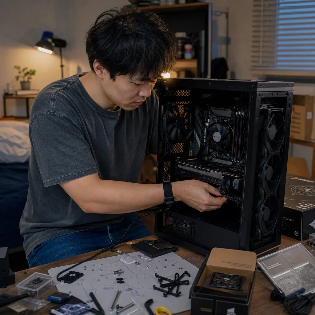
The I/O shield looks like a small, simple piece of metal, but it can create a surprisingly frustrating problem. Install it backward, catch a spring tab inside a USB port, or overlook a misplaced standoff, and the motherboard may need to come back out of the case.
The safest approach is to treat the shield as part of the case installation, not as an afterthought. Work slowly, confirm the shield’s orientation before pressing it into place, and test the motherboard’s fit before tightening anything. That extra minute is much easier than correcting a blocked port after the board is installed.
First, identify which kind of I/O shield you have
Many motherboards use a separate rectangular shield that snaps into the back of the case. It has cutouts for the rear ports and may have small spring tabs around those openings. This is the type that requires careful installation before the motherboard goes into the case.
Some newer motherboards have an integrated I/O shield permanently attached to the motherboard. You won’t install a separate metal plate with this design. Instead, the attached shield slides into the case’s rear I/O opening as you lower the motherboard into position. Don't try to remove it or force the board through an opening that appears too small; check whether the case supports the board and its integrated shield.
If a separate shield came with the motherboard, use that shield rather than one from another board. The port layout and tab placement are specific to the motherboard’s rear connectors. A shield that looks similar may not align correctly, and a generic replacement can leave ports blocked or poorly supported.
Confirm the shield before opening the case: Check whether your motherboard has a separate I/O plate, an integrated shield, or a case-mounted solution. If the manual shows a different arrangement, follow that design instead of treating every rear panel the same way.
Prepare the case before pressing anything into place
Set the case on a stable surface with enough room to work. Remove the side panels and, if they obstruct access, any removable cable-management panels or drive brackets. You need to see both the back of the case and the motherboard tray without leaning over a cluttered workspace.
Keep the motherboard nearby, but don’t install it yet. Compare the rear connector layout on the board with the openings in the I/O shield. This gives you a useful orientation check: the shield’s printed labels and port shapes should match the board when the board is viewed from behind, not from the front of the case.
Inspect the case’s motherboard tray for standoffs. The standoffs should correspond to the mounting holes in the motherboard’s form factor. A standoff under an area with no mounting hole can press against the back of the board and cause damage when the screws are tightened. A missing standoff can leave part of the board unsupported, but adding extras isn't a safe substitute for checking the hole pattern.
Don't rely only on the number of standoffs already installed. Cases sometimes arrive with a common pattern that doesn’t match every ATX, microATX, or Mini-ITX board. Move or remove any standoff that doesn’t align with a motherboard mounting hole before the board goes in.
Install the separate shield without bending the tabs
Hold the shield by its edges. The metal can be sharp, so avoid sliding your fingers along the cutouts. Position the shield from the inside of the case, with the printed labels facing outward toward the back of the case. The shield should fit into the large rectangular opening in the rear panel.
Start with one edge rather than pressing the entire plate at once. Seat the edge with the least complicated shape, then work around the perimeter with your fingertips. Apply pressure near the solid metal rim, not directly on the thin spring tabs. You should hear or feel the retaining clips engage as the shield snaps into the case.
A properly installed shield sits flat and even with the surrounding rear panel. The edges should be held by the case’s retaining lips, and the port openings should remain open. If one corner refuses to seat, remove the shield and inspect the opening rather than increasing pressure. A slightly misaligned shield can make the final corner seem impossible to fit.
The spring tabs are the main source of trouble. They are intended to contact the outside surfaces of the motherboard’s rear connectors, but they can fold into a connector opening if they are positioned poorly. Before installing the motherboard, look through every port cutout from the outside of the case. If a tab extends into an opening, gently move it so it rests against the outer edge of the corresponding connector area.
Don’t cut off all the tabs just because one is inconvenient. They can help maintain contact around the rear connectors, and removing metal changes the shield from the way its manufacturer designed it. If a particular tab clearly interferes with a port, compare its position with the motherboard and shield instructions first. A tab may need to be bent slightly outward, but it shouldn’t be folded into a USB, network, audio, or video connector opening.
Test the fit before securing the motherboard
With the shield installed and the standoffs checked, lower the motherboard into the case at a slight angle. Usually, the rear connectors need to enter the I/O shield first while the board’s mounting holes move toward the standoffs. Keep the motherboard level enough that it doesn’t scrape across the standoffs.
Use the edges of the board and its mounting holes to guide it. Never push down hard on the rear ports to make them pass through the shield. If the board doesn’t settle into position, lift it back out and identify what is stopping it. Common causes include a spring tab caught inside a port, a shield installed upside down, or a case opening that doesn’t match the board’s layout.
Once the board is resting in the case, look at the rear I/O area from outside. Each connector should be centered within its opening, and no metal tab should cover the opening or sit inside a port. From inside the case, confirm that the mounting holes are directly above the standoffs. The board shouldn't need to be pulled sideways to make the holes line up.
This is also the point to check clearance around the audio jacks, network connector, USB ports, and any rear antenna connectors. Some connectors have metal shells that can catch on a shield tab even when the board appears nearly aligned. If anything looks forced, remove the motherboard and correct the shield rather than using screws to pull the board into place.
Check alignment before adding screws: Verify every rear port, every motherboard mounting hole, and every standoff while the board is still easy to remove. If one of those checks fails, fix the obstruction now instead of tightening the motherboard around it.
Tighten the board without using screws as a clamp
After the board is correctly positioned, install the motherboard screws loosely. Start with a central mounting point if the case layout allows it, then add the remaining screws. The goal is to hold the board in place while preserving its natural alignment, not to drag a misaligned board toward the standoffs.
Once all screws are started, tighten them gradually in a pattern that spreads pressure across the board. They should be snug, not excessively tight. A screw that turns indefinitely may indicate a spinning standoff or a missing thread, while a screw that requires unusual force deserves investigation. Avoid using an electric driver at high torque near the motherboard.
After tightening, inspect the rear ports again. The shield shouldn’t have shifted enough to block a connector, and the board shouldn’t be under visible stress. If a port has become difficult to access, remove the motherboard and inspect the shield rather than enlarging the case opening or forcing a plug into place.
Common edge cases to handle carefully
A case may include a removable I/O bezel, a sliding rear bracket, or a retaining frame instead of the usual snap-in shield. In that situation, the case instructions take priority because the frame may be designed to remain attached while the motherboard is installed. Don’t add the separate motherboard shield if the case’s rear opening already has a purpose-built system that occupies the same space.
Some shields include foam or fabric-like material around the openings. That material may provide cushioning or help close small gaps. Leave it in place unless the motherboard or case instructions specifically say otherwise. Peeling it away can expose edges or reduce the shield’s ability to sit securely.
A board with unusually large rear connectors, built-in antenna structures, or an integrated shield may need to enter the case at a different angle than a conventional board. Take a moment to study the path before lowering it. You may need to remove a case fan, cable guide, or other obstruction temporarily, but you shouldn’t have to bend the rear panel to make the board fit.
If the shield pops out when you remove the motherboard, don’t treat that as proof that it was defective. It may not have been fully engaged with the case’s retaining lips. Reinstall it with the motherboard removed and press around the solid perimeter until each side is held firmly.
The reliable sequence
The safest sequence is straightforward: identify the shield type, match it to the motherboard, inspect the case opening, verify the standoff pattern, and install the separate shield before lowering in the board. Then check every tab and port from the outside, confirm the mounting holes line up, and only afterward start and tighten the screws.
If the motherboard doesn’t fit smoothly, stop and find the obstruction. Most I/O shield problems are easier to solve with the board in your hands than after cables, graphics cards, and storage devices are installed. A careful fit check at the beginning protects the ports, reduces stress on the motherboard, and saves you from the particularly annoying job of removing a nearly finished build.