How to Check Expansion Card Clearance Around a Large CPU Cooler
I’ll compare the measurements, diagrams, and physical checks that reveal whether a large CPU cooler will interfere with your expansion cards, backplates, or installation access. You’ll learn which clearances matter most and how to avoid discovering the conflict after the motherboard is mounted.
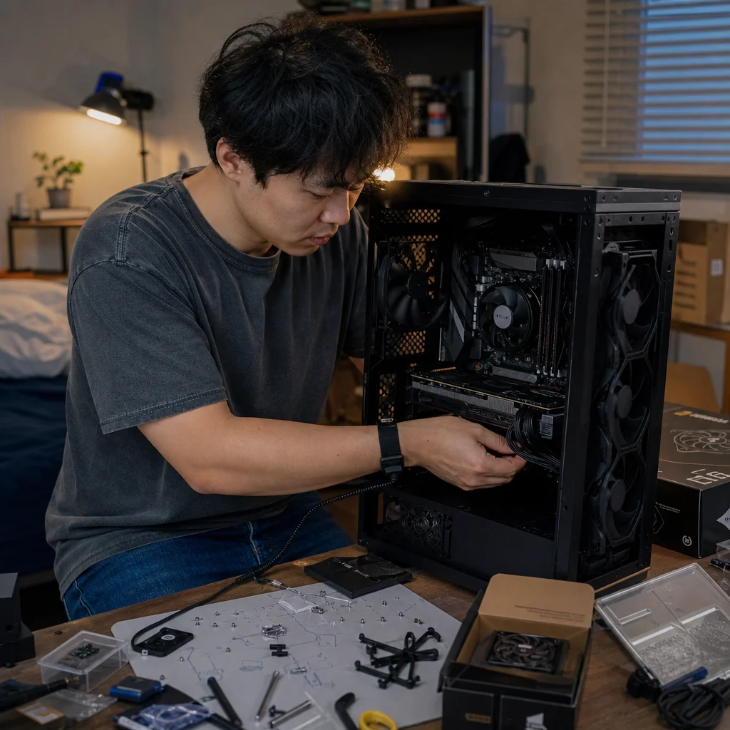
A large tower cooler can fit within a case and still create a problem for an expansion card. The issue usually comes from the space around the motherboard’s PCIe slots: a cooler may overhang the top slot, crowd a graphics card’s backplate, or make it difficult to secure and remove the card.
The safest approach is to treat clearance as a three-dimensional measurement rather than a simple question of whether the motherboard and cooler are individually compatible. You need to compare the cooler’s shape with the motherboard’s slot layout, then account for the expansion card’s height, thickness, and installation path.
Start with the motherboard’s slot layout
Find the motherboard’s manual or technical drawing and identify the primary full-length PCIe slot. On many boards, this is the uppermost long slot, but its position relative to the CPU socket can vary. Some boards leave more space between the socket and the slot; others place the slot close enough that a wide cooler heatsink or fan may overlap it.
Don't judge the layout only by counting empty slots. A cooler that extends over the first slot may still leave the slot electrically usable, but the card installed there could touch the cooler or become impossible to release. A graphics card installed in the second full-length slot may avoid the cooler, but that slot may have different bandwidth, share lanes with another device, or be physically blocked by the case layout.
Pay attention to the CPU socket’s position as well. Socket placement can shift between motherboard models, even when they use the same processor platform. The distance from the socket center to the top expansion slot is therefore more useful than a general statement such as “this cooler fits ATX boards.”
Also inspect nearby motherboard hardware. Tall heatsinks around the CPU socket, memory slots, M.2 heatsinks, and reinforced slot latches can all affect the path you need to install or remove an expansion card. These parts may not prevent the card from operating, but they can make the build awkward or require removing another component first.
Compare the cooler’s actual footprint, not just its height
Cooler height mainly tells you whether the side panel will close. It doesn't tell you whether the heatsink extends toward the expansion slots. For this check, you need the cooler’s width and depth, plus the position and adjustment range of its fan.
A tower cooler may have a heatsink body that overhangs the memory slots or the top edge of a graphics card. Its front fan can add several millimeters to that footprint, and the fan may be mounted lower or higher on its clips. A cooler that looks acceptable without the fan can become a clearance problem once the fan is installed in its normal position.
Check the manufacturer’s drawings for the heatsink outline and the distance from the CPU contact area to each edge. If a drawing isn't available, use the cooler’s physical dimensions as a starting point, but treat them as an approximation. Overall width and depth don't always show where the fin stack, heatpipes, clips, or fan actually sit.
The cooler’s mounting orientation matters too. Some models can be rotated so the fin stack points toward the top or rear of the case. That may improve expansion-card clearance, but it can change memory clearance, rear exhaust spacing, or the direction in which the fan needs to move air. Use only orientations supported by the mounting hardware and installation instructions.
Confirm the dimensions before you buy: Compare the exact cooler model, fan position, and motherboard drawing with the expansion card you plan to install. Product pages sometimes show family-level compatibility, while the detailed manual or dimension diagram reveals the measurements that determine whether the parts actually coexist.
Measure the expansion card as a three-dimensional object
Expansion cards are commonly described by their slot width, but that is only one part of the clearance problem. A card may occupy two, three, or more rear-slot positions while extending farther toward the motherboard than its bracket suggests. A large graphics card may also have a raised backplate, reinforcing frame, heatpipe, or power connector that changes the required space.
For cooler clearance, focus on the card’s height above the motherboard and the distance from its edge to the CPU cooler. The motherboard-facing side of a graphics card can sit close to the cooler’s lower fin stack. A backplate may be flat, but it still adds thickness; a backplate with a raised section can come closer to the heatsink than the bare PCB would.
Power connectors deserve special attention. If the card’s power socket faces upward, the cable may need room between the card and the cooler or side panel. A connector that technically fits can still be under excessive bending pressure if the cooler leaves no space for the cable to route naturally. The required bend radius depends on the connector and cable design, so follow the card and power-supply maker’s guidance rather than forcing the cable into a sharp fold.
Consider the card’s removal path, not just its final position. You may need to press the motherboard’s PCIe latch, loosen the rear bracket screws, and lift the card straight out. A cooler fin stack or fan directly above the latch can turn routine maintenance into a difficult maneuver. If reaching the latch requires a tool, protect the motherboard from slips and avoid levering against fragile components.
Use the slot positions to find the likely conflict
A simple way to organize the check is to map the parts in layers:
- Mark the CPU socket center and the top edge of the expansion slots on the motherboard diagram.
- Mark the cooler’s fin-stack and fan footprint around the socket.
- Mark the expansion card’s height, thickness, backplate, and connector locations.
- Add the case’s rear-slot alignment and side-panel clearance.
The most common conflict is between the cooler’s lower edge and a card installed in the uppermost full-length slot. If the cooler overlaps that slot, determine whether the overlap is merely above an empty section of the card or directly above its backplate, heatsink, or power connector. A few millimeters of apparent overlap may be harmless in one layout and impossible in another.
A card installed in a lower slot may solve the physical conflict, but it isn't automatically an equivalent solution. Check the motherboard manual for slot bandwidth, processor-versus-chipset connectivity, lane sharing, and support for the card’s intended function. This is especially important for graphics cards, high-speed network adapters, capture cards, and storage controllers.
You should also account for the card’s thickness below the slot. A graphics card that uses multiple slots can cover adjacent connectors or leave little room for another card. If moving the primary card downward causes it to cover a smaller expansion slot, front-panel connector, or airflow opening, the change may trade one clearance issue for another.
Account for the case and installation order
The case sets the outer boundaries, but it doesn't solve motherboard-level interference. Confirm the cooler’s maximum height against the case specification, then check whether the case has enough rear expansion positions and internal room for the card’s length and power cables. These are separate checks from the space between the cooler and the card.
Installation order can expose problems that a static measurement misses. A large cooler may block the top PCIe latch once installed, making it sensible to install the expansion card before the cooler. However, the card may then prevent access to cooler mounting screws or make it difficult to position the heatsink safely. If both components are large, test the sequence on the motherboard outside the case when possible.
Don't install a heavy graphics card while the motherboard is flexing or poorly supported. Place the board on its box or another clean, nonconductive surface intended for temporary assembly, and support the cooler while handling the board. Avoid resting a heatsink or card on exposed connectors. The goal isn't only to make the parts fit, but to avoid damaging the board while trying to reach a hidden latch or screw.
After installation, inspect the area from several angles. Look for direct contact between metal fins and the card’s backplate, pressure on a fan frame, blocked latch movement, and cables touching fan blades. A small gap is preferable to contact, but don't assume every visible gap is sufficient if the parts can move during handling or transport.
When a close fit is acceptable—and when it isn't
A close fit can be workable when the cooler and card are securely mounted, there is no contact, airflow paths remain open, and you can still service the latch and mounting hardware. The card shouldn't be wedged into place or held against the cooler by the case bracket. Fans should spin freely without cable interference, and the side panel should close without pressing on a cable or component.
Treat physical contact as a stop sign. Don't rely on a thin insulating pad, tape, or improvised spacer to separate a cooler from a card. Such additions can shift, retain heat, obstruct airflow, or interfere with the card’s mounting. If the parts touch, change the orientation, move the card to a suitable slot, adjust the cooler’s supported fan position, or select a different cooler or expansion card.
A few millimeters of clearance also may not be enough around moving parts and connectors. Fans need unobstructed intake space, and power cables need room to connect without sharp bends or sideways pressure. Service access matters over the life of the system: dust cleaning, card replacement, and troubleshooting are much easier when you can reach the relevant fasteners without dismantling half the computer.
Practical ways to prevent the problem
The most reliable method is to compare exact model drawings before ordering. Use the motherboard’s socket-to-slot layout, the cooler’s edge and fan dimensions, and the expansion card’s published thickness and backplate details. If one manufacturer provides only broad compatibility labels, look for a detailed installation manual or a dimensioned drawing rather than assuming the label covers every physical arrangement.
If the measurements are close, make a simple full-scale template from cardboard. Mark the CPU socket position, cooler footprint, top of the motherboard, and card profile. This won't reproduce every heatsink or cable detail, but it can reveal whether the major shapes overlap. You can also temporarily place the motherboard, cooler, and card together before final cable management, provided you handle the components carefully and follow normal static-safety precautions.
When choosing between approaches, prioritise a layout that leaves the primary expansion slot usable without special contortions. Moving a card to a lower slot may be sensible if the motherboard provides the required connectivity and the case preserves airflow. Adjusting a cooler fan can be a clean solution when it remains within the cooler’s supported range and doesn't crowd the memory modules or side panel. Replacing a cooler is often preferable to accepting contact or losing routine access to the card latch.
Before final assembly, verify that the card is fully seated, its rear bracket is aligned, its retaining screw is secure, and its power cable is connected without strain. Confirm that the cooler fan and any nearby case fans can spin freely. If the cooler and expansion card remain separate, accessible, and properly supported after these checks, you have solved the clearance problem rather than merely squeezing the parts into the case.