How to Validate PCIe Slot and Lane Sharing Before Buying Storage or Capture Hardware
I’ll compare the slot, lane, and bandwidth details that matter when you’re choosing NVMe storage or capture hardware, then show you how to use the motherboard manual to avoid disabled slots, reduced speeds, and expensive compatibility surprises.
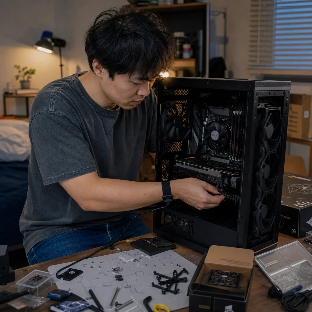
Buying an expansion card based only on the slot’s physical size is an easy way to create a compatibility problem. A motherboard may provide several long PCIe slots, but some can share lanes, lose bandwidth, or become unavailable when an M.2 socket or another expansion slot is populated.
The reliable approach is to validate the complete lane map before you buy. You need to know which device will use which slot, where those lanes come from, what happens when another device is installed, and whether the resulting connection is sufficient for the hardware’s requirements.
Start with the device requirements
First, identify the electrical PCIe requirement for each planned device, not just its connector shape. An expansion card with a physically long x16 connector might operate electrically at x4 or x8. A storage adapter could need only four lanes, while a multi-port capture card, high-speed network adapter, or workstation controller may specify x4, x8, or x16 operation.
The card’s required PCIe generation matters too. PCIe is generally backward-compatible across generations, so a newer card can often operate in an older slot. However, it will use the older link’s bandwidth when doing so. A device that works at PCIe 4.0 x4 will have less theoretical bandwidth at PCIe 3.0 x4, even though it may remain functional.
Look for the manufacturer’s installation requirements rather than relying on a product photo or a retailer’s short specification table. Pay attention to minimum lane width, supported generations, recommended slot position, cooling clearance, and any requirement for a CPU-connected slot. Some cards work in a narrower link but lose performance; others may not support their full feature set below a stated lane width.
For storage, also distinguish between an M.2 drive installed directly on the motherboard and an NVMe drive placed on a PCIe adapter card. The motherboard may route an M.2 socket through the chipset, while a full-size expansion slot may receive lanes directly from the processor. Those paths can have different bandwidth and sharing rules.
Read the motherboard manual’s lane map
The motherboard manual is usually the most useful source because it explains the board’s slot behavior as a system. Find the sections titled something like “PCIe slots,” “expansion slots,” “storage,” “M.2,” or “block diagram.” The exact labels vary by manufacturer and model.
Don't stop at the specifications page that says a board has two x16 slots and three M.2 sockets. That description often identifies the physical connectors, not the number of lanes available to all of them simultaneously. The manual’s tables and diagrams are more likely to show whether the second long slot runs at x8, x4, or no connection under particular conditions.
Trace each planned device through the diagram. A typical platform might provide a group of CPU lanes to the primary graphics slot and another group to a second expansion slot. The chipset may provide additional PCIe connectivity for lower-priority slots, M.2 sockets, networking, and USB controllers. That arrangement differs by processor platform and motherboard design, so assumptions from another board aren't safe.
Terms such as “shares bandwidth,” “shares lanes,” and “disabled when populated” aren't interchangeable. Sharing may mean that two slots divide a fixed group of lanes. It may mean that one device switches from x4 to x2. It may also mean that inserting a drive into a particular M.2 socket disables a SATA port or a PCIe slot entirely. Find the specific consequence for the slot and device you intend to use.
Confirm your board’s exact lane table: Open the manual for your precise motherboard revision and processor platform, then verify every planned slot and M.2 socket in the installation combinations you’ll actually use. Product pages and general chipset diagrams may omit the disabling or lane-width rules that determine the result.
Build a simple connection plan
Before comparing products, write down the hardware that must be installed. Include the graphics card, NVMe drives, capture cards, network adapters, storage controllers, sound cards, and any PCIe expansion card you may add later. Mark the slot each device is likely to occupy and record the device’s required or preferred link width.
A small table can make the relationships clear:
| Device | Planned connector | Electrical requirement | Possible dependency |
|---|---|---|---|
| Graphics card | Top long slot | Often x16, but check the card and platform | May share CPU lanes with another long slot |
| NVMe adapter | Long or short slot | Commonly x4, depending on the adapter | May share chipset lanes or require bifurcation |
| Capture card | Usually x4 or x8 | Check the manufacturer’s specification | May need a slot that remains active with M.2 drives populated |
| Motherboard M.2 drive | M.2 socket | Fixed by the board’s design | Can disable a slot, SATA port, or another M.2 socket |
The table isn't a substitute for the manual. It gives you questions to answer. For example, if the capture card needs x4 and the only available x4-capable slot is disabled when the third M.2 socket is populated, you need to change the storage layout or choose a different motherboard.
Also consider physical placement. A graphics card can cover a lower slot, and a thick cooler can prevent access to an adjacent connector. A slot that is electrically suitable may be unusable after the graphics card, drive heatsinks, and case expansion brackets are installed. Workstation builds often have enough devices to make physical clearance as important as lane allocation.
Understand the common sharing patterns
One common design splits processor lanes between two long slots. With one card installed, the primary slot may run at x16. When a second card is installed, both may run at x8. This can be perfectly reasonable for some workloads, but it isn't equivalent to having one x16 connection and one independent x8 connection.
Another design leaves the graphics slot at x16 but routes secondary slots through the chipset. Those slots may operate at x4 or another narrower width and share the chipset’s connection to the processor with storage, USB, networking, and other devices. The devices can still work, but simultaneous transfers may compete for shared upstream bandwidth.
Some motherboards disable a slot when a particular M.2 socket is occupied. This is often a design choice rather than a fault: the board is assigning the same physical lane resources to two connectors. The manual may state that using one M.2 socket disables SATA ports, a lower PCIe slot, or another M.2 socket. Treat “supports four M.2 drives” and “supports four M.2 drives plus every expansion slot at full operation” as different claims.
You may also encounter lane bifurcation. Bifurcation divides a group such as x16 into smaller links, for example x4/x4/x4/x4, so a compatible adapter can address multiple devices. The motherboard and firmware must support the needed division, and the adapter must be designed to expose the devices correctly. A passive adapter doesn't automatically make four drives visible just because the slot has sixteen physical lanes.
Calculate enough bandwidth to spot bad assumptions
PCIe link speed is determined by generation and lane width. Each generation increases the transfer rate per lane, while x4, x8, and x16 describe how many lanes are in the link. The usable data rate is lower than the raw signaling rate because of encoding and protocol overhead.
For planning, the approximate one-direction raw rates per lane are useful as a sanity check: PCIe 3.0 is about 1 GB/s, PCIe 4.0 about 2 GB/s, and PCIe 5.0 about 4 GB/s. Multiply by the active lane count for a rough maximum before overhead. Actual storage and capture performance depends on the device, protocol, workload, chipset path, and other traffic.
This calculation helps expose a common mistake: treating PCIe 4.0 x4 and PCIe 3.0 x4 as equivalent because both are x4. They have the same lane count but different per-lane rates. Similarly, a PCIe 4.0 x2 connection can provide roughly half the link bandwidth of PCIe 4.0 x4, even if the drive or card is installed in the same physical connector.
Don't assume that a device needs the largest available slot. A capture card’s requirement might be x4, making a full-length slot with four active lanes sufficient. Conversely, don't assume that a long slot offers x16 electrically. Confirm the negotiated width and generation the card is designed to use.
Check firmware, bifurcation, and platform limits
The manual may describe supported configurations, but firmware settings can affect how devices are exposed. If you are using a multi-drive adapter, look for the board’s bifurcation options and the adapter’s compatibility information. Some systems support only certain divisions on a particular slot, while others require a firmware mode intended for a specific type of carrier card.
Processor choice can matter as much as motherboard choice. A board may expose different lane arrangements depending on the installed CPU, and a platform’s chipset may offer a fixed number of downstream connections. A processor with fewer available PCIe lanes can change the behavior of a secondary slot or prevent a promised configuration from operating at its maximum width.
When a manual uses phrases such as “up to,” “depending on CPU,” or “when M.2_2 is occupied,” treat those words as configuration conditions, not marketing decoration. Record the exact CPU, motherboard model and revision, firmware notes, and devices involved. This is especially important when a workstation build is being planned around several high-bandwidth cards.
Validate the assembled system after installation
After assembly, inspect the negotiated link for each important device. Many firmware interfaces show the active slot mode, and operating systems can report the negotiated PCIe generation and lane width through hardware-information utilities. The expected result might be PCIe 4.0 x4 rather than the slot’s maximum of PCIe 5.0 x16.
A lower link width isn't automatically a problem. A device may deliberately use fewer lanes, or the platform may reduce link speed during idle operation. Check while the device is active and compare the result with the motherboard and card requirements. If a capture card is detected but behaves poorly, or an NVMe drive performs far below its expected interface class, link negotiation and sharing should be among your first checks.
If a device is missing, power down and revisit the manual before moving cards randomly. Check whether populating an M.2 socket disabled the slot, whether the card is fully seated, whether auxiliary power is required, and whether the firmware recognizes the configuration. Moving a card to a different connector can solve the problem, but only if that connector has the lanes, clearance, and bandwidth the device needs.
Choose the board by the complete layout
The best motherboard isn't necessarily the one with the most connectors. It is the one whose lane map matches your complete build with acceptable compromises. If you need a graphics card, several NVMe drives, and a capture card, a board that keeps the capture card on an active x4 or x8 connection may be more useful than one that advertises an extra M.2 socket but disables your only suitable expansion slot.
Make the lane plan before buying storage or capture hardware, and leave room for the device you are most likely to add later. Verify the exact manual, account for your processor, check physical clearance, and confirm the negotiated links after installation. That small amount of planning prevents the most expensive version of a compatibility mistake: discovering that the hardware fits the case but not the motherboard’s available lanes.