How Motherboard Slot Sharing Can Change Your Build Plan
I’ll compare the motherboard slot-sharing arrangements that affect M.2 drives, graphics cards, and expansion cards, then show you how to read the manual, identify real bandwidth trade-offs, and choose parts without paying for connections your build can’t use together.
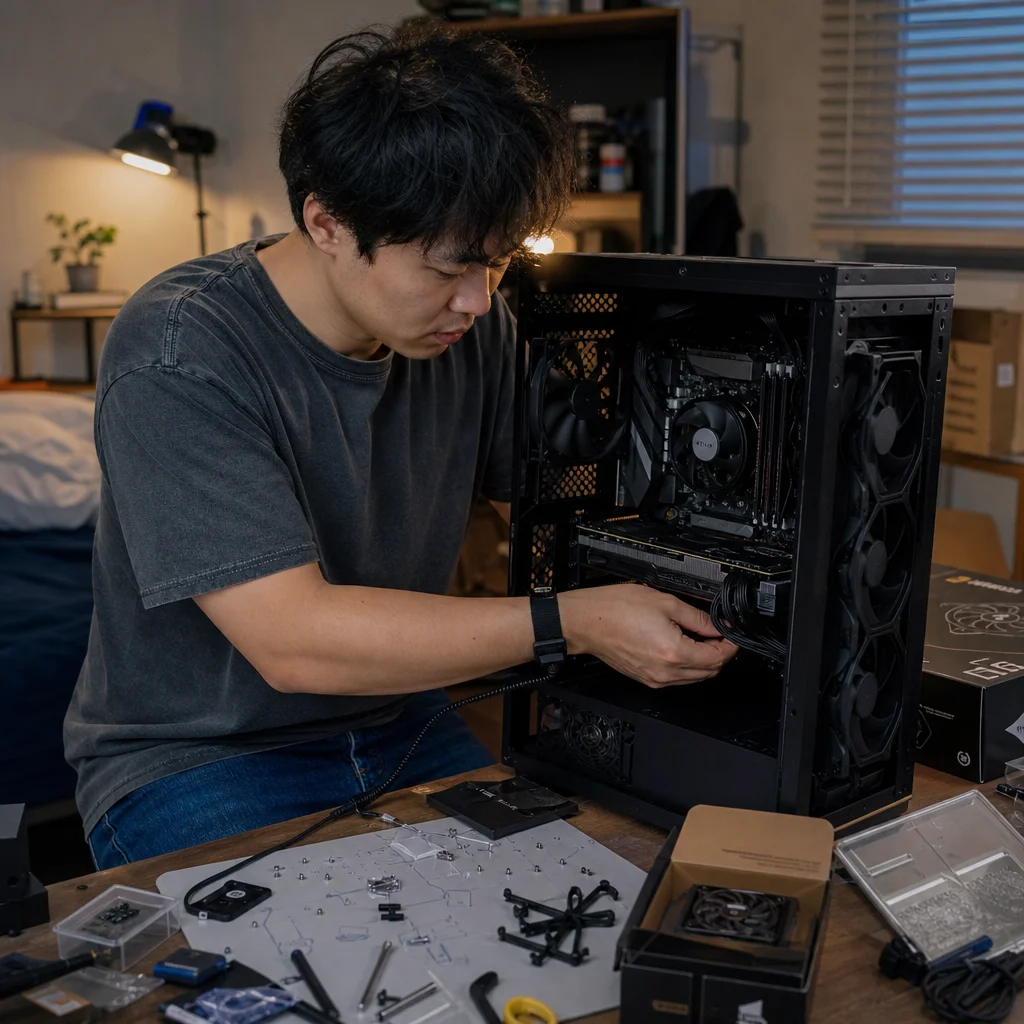
Adding an M.2 SSD or expansion card can look like a simple way to improve a PC. Sometimes it is. On some motherboards, however, populating one slot changes how another slot works: a SATA port may be disabled, an expansion slot may drop to fewer lanes, or a second M.2 connector may share bandwidth with other devices.
That behavior is called slot sharing, though motherboard manuals may describe it as shared bandwidth, lane sharing, lane bifurcation, or resource allocation. It doesn’t mean the board is defective. It means the processor and chipset provide a finite number of data lanes, while the board offers more physical connections than all of them can always support at full speed.
Understanding that limit before you buy parts can prevent a frustrating choice between storage capacity, graphics performance, and expansion flexibility.
What slot sharing actually means
PCI Express devices communicate through lanes. A connection can use one lane, two, four, eight, or sixteen lanes, depending on the device and the motherboard slot. An M.2 NVMe drive commonly uses up to four PCIe lanes, while a graphics card is usually installed in a full-length slot designed for sixteen lanes, even though it may operate with fewer in some configurations.
The visible connector doesn’t tell you the whole story. A full-length PCIe slot might be electrically connected with only four lanes. An M.2 socket might support a PCIe drive, a SATA M.2 drive, or both. Two physical slots might draw lanes from the same underlying connection, so using one forces the other to change behavior.
Sharing can take several forms:
- One connection is disabled when another is populated.
- Two devices remain active but divide available lanes or bandwidth.
- A slot changes from x16 to x8, or from x4 to x2.
- A SATA port becomes unavailable when a particular M.2 socket is used.
- A device moves through the chipset rather than receiving lanes directly from the processor.
These are different outcomes. A disabled SATA port is a compatibility detail. A graphics slot dropping from x16 to x8 is a performance consideration. A chipset-connected SSD sharing an uplink with USB devices is a broader bandwidth arrangement that may only matter during simultaneous heavy transfers.
The main connections you need to map
Your build plan is easier to evaluate when you separate the motherboard’s connections by where their lanes come from. On many modern desktop platforms, the processor provides a dedicated group of PCIe lanes for the primary graphics slot and one or more high-speed storage connections. The chipset provides additional lanes for secondary expansion slots, M.2 sockets, SATA controllers, USB, networking, and other integrated devices.
That layout varies by processor platform and motherboard generation, so treat it as a way to reason about the board rather than a universal specification. The important question isn't simply how many slots appear on the product page. It is which devices share resources and which connections are independent.
The primary graphics slot is often the connection you want to protect first. If installing a second M.2 drive causes the main graphics slot to operate at x8 instead of x16, that may be an acceptable trade-off—or it may be an avoidable one. If a second expansion card causes the graphics slot to drop to x8, the answer depends on the card, your workload, and the platform’s available bandwidth.
Secondary full-length slots are especially easy to misread. Their physical size may suggest that they are suitable for another graphics card or a fast storage adapter, but their electrical connection may be x4 through the chipset. That can be perfectly adequate for a capture card, network adapter, or additional SSDs. It may be less suitable for a device that expects a high-bandwidth, low-latency connection.
M.2 sockets deserve their own inspection. A socket labeled for PCIe x4 may disable one or more SATA ports when used. Another socket may share lanes with a full-length PCIe slot. A third may connect through the chipset and compete for the chipset-to-processor uplink. The labels near the sockets are useful clues, but the block diagram and storage table are more reliable.
Why adding an M.2 drive can change the plan
M.2 describes the physical form factor, not the communication protocol. An M.2 socket may accept an NVMe PCIe drive, a SATA M.2 drive, or only one of those types. The drive’s keying and the socket’s specifications determine whether it is compatible, while the motherboard’s lane map determines what else changes when you use it.
A common arrangement connects an M.2 socket to lanes that are also assigned to several SATA ports. When you install an NVMe drive, those SATA ports are disabled because the board’s controller can't use the same resources for both connections. Nothing is being slowed; the ports simply stop being available. This matters if you planned to attach a hard drive, SATA SSD, optical drive, or front-mounted storage cage.
Another arrangement shares an M.2 socket with a PCIe slot. Installing the drive may reduce that slot’s lane width or disable it. If the affected slot is unused, there may be no practical consequence. If it contains a capture card, sound card, storage adapter, or network card, you need to account for the change.
A third arrangement leaves every device active but routes several chipset-connected devices through the same uplink to the processor. In that case, the devices can work at the same time, but their combined traffic is limited by the shared path. This is usually more relevant to simultaneous workloads—such as copying files between multiple drives while using several high-speed USB devices—than to ordinary game loading or general desktop use.
How graphics-slot changes affect performance
The phrase “runs at x8” often sounds more alarming than it is. PCIe x8 isn't automatically a problem, and the impact depends on the PCIe generation, the graphics card, the application, and whether the card is actually transferring data across the bus during the workload. A newer PCIe generation can provide more bandwidth per lane than an older one, so lane count alone doesn’t provide a complete answer.
Still, you shouldn’t treat a change from x16 to x8 as irrelevant. It can reduce the available link bandwidth, and some workloads or devices will make better use of that bandwidth than others. The sensible approach is to identify the change in advance, then decide whether the affected device justifies keeping the faster arrangement.
For a single graphics card, the primary slot is normally the starting point. If you’re adding an expansion card, check whether it can be installed in a slot that doesn’t share resources with the graphics connection. If the only available slot changes the graphics link, compare that cost with the card’s actual needs. A modest peripheral may not justify rearranging the whole build, while a high-throughput storage or accelerator card might.
Also check the slot’s physical clearance. A thick graphics card can cover adjacent slots or M.2 heatsinks, making a technically compatible layout unusable. Slot sharing is an electrical constraint, but the final build plan has to satisfy physical constraints as well.
How to read the motherboard documentation
Start with the motherboard manual, not a retailer’s short specifications list. Product pages often summarize maximum slot configurations but omit the exact conditions under which a connector is disabled or reduced. Look for sections titled “Storage,” “Expansion Slots,” “PCIe Configuration,” “Block Diagram,” or “Switches and LEDs.”
The table may use notation such as “M2_2 shares bandwidth with SATA_5/6” or “When PCIEX16_2 is populated, PCIEX16_1 operates at x8.” Translate each statement into a build consequence. Which device becomes unavailable? Does the change affect a physical slot, a protocol, or only a subset of SATA ports? Does it apply to a particular processor model?
Pay attention to footnotes. Some boards have different lane arrangements with different processor families. A socket may support four PCIe lanes with one processor but only two with another, or a secondary slot may be unavailable on a lower-lane processor. Firmware settings can also affect slot behavior, although they can't create lanes the platform doesn't provide.
A block diagram can be more informative than a list of specifications. Trace the primary graphics slot, each M.2 socket, the secondary PCIe slots, and the chipset uplink. You don’t need to memorize the electrical design. You’re looking for connections that converge on the same resource.
Confirm your board’s exact lane map: Before buying the second SSD or expansion card, open the manual for the precise motherboard revision and processor combination. Record which M.2 sockets disable SATA ports, which slots share the graphics link, and which sockets accept NVMe versus SATA drives; manufacturers can change details between models and revisions.
A sensible way to plan your parts
Begin by listing the devices you actually intend to install, rather than every connection the motherboard advertises. Include the graphics card, all M.2 drives, SATA drives, expansion cards, front-panel storage requirements, and any adapter that occupies a PCIe slot. Note which devices are essential and which are optional.
Next, assign each device to a connection. Put the graphics card in the recommended primary slot, then test the storage layout against the manual’s sharing notes. If an M.2 drive disables SATA ports you need, move the drive to another socket, use a different storage interface, or select a board with a more suitable lane arrangement.
This is also where cost and resource efficiency matter. You may not need a more expensive motherboard simply because it has more slots. A board with fewer connectors can be the better choice if it supports your actual devices without conflicts. Conversely, saving money on the board can be false economy if it forces you to replace a planned SSD, add an adapter, or abandon a useful expansion card later.
When two arrangements are valid, prefer the one that preserves flexibility. For example, using a chipset-connected M.2 socket may be sensible for a secondary game library, while keeping a processor-connected socket available for a drive used for demanding work. The distinction isn’t that one drive is universally “better”; it’s that assigning devices according to their workload can avoid unnecessary contention.
Common planning mistakes
One mistake is counting connectors instead of checking their relationships. A board can have three M.2 sockets and six SATA ports while still making some combinations unavailable. Another is assuming that every full-length PCIe slot provides x16 electrical bandwidth. The slot’s physical shape and its lane allocation are separate facts.
It’s also easy to overlook SATA M.2 compatibility. A drive that fits the M.2 shape may not communicate with a socket that supports only PCIe NVMe devices. Conversely, installing a SATA M.2 drive in a socket that shares SATA resources may disable ports without providing the performance benefit you expected from NVMe.
Avoid relying on a generic diagram from a similar motherboard. Two boards using the same chipset can route lanes differently, and a revision may change the available configuration. Check the exact model, revision where relevant, and processor family.
Finally, don’t assume that a slower link is always visible in everyday use—or that it never matters. A graphics card, storage adapter, and network card have different traffic patterns. Evaluate the consequence against your workload instead of making a decision from the lane number alone.
The practical takeaway
Slot sharing becomes manageable when you treat the motherboard as a resource map rather than a collection of independent sockets. Identify where the processor and chipset provide lanes, find the connections that share them, and translate each manual note into a consequence for your specific parts.
Before finalizing the build, verify the graphics-slot mode, M.2 protocol support, SATA ports affected by each socket, secondary-slot lane widths, and any processor-specific limitations. Then choose the arrangement that keeps the devices you value most on the connections they actually need. That approach can save money, preserve upgrade options, and prevent a finished system from revealing its compatibility rules only after everything is installed.