How to Use a Case Manual to Catch a Build Problem Before Ordering
I’ll show you how to read a PC case manual as a compatibility document, not just an assembly reference. You’ll learn where to check GPU, radiator, drive, fan, power-supply, and front-panel details before ordering parts that may not fit together.
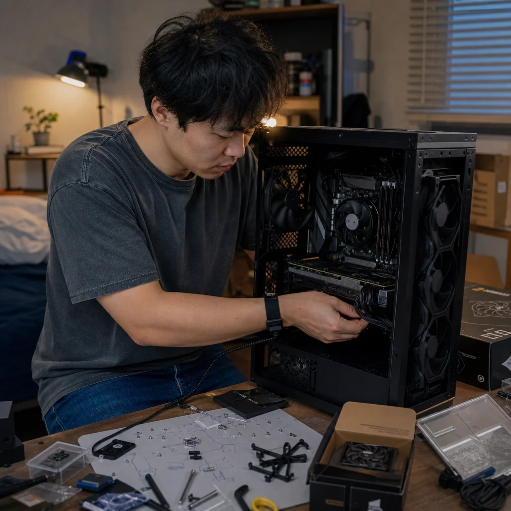
A case can look roomy in photographs and still create a problem for your build. A graphics card may fit only without a front radiator, a power supply may leave too little room for cables, or the front-panel connectors may not match the features you expect to use.
The case manual is where those details usually become measurable. Even a short PDF can reveal restrictions that a product page summarizes too broadly. Reading it before ordering lets you test the build on paper, while changing a component is still easier than returning assembled hardware.
Start with the manual, not the product photos
Find the manual from the case manufacturer, preferably for the exact model and revision. Product pages often list headline dimensions such as maximum graphics-card length or CPU-cooler height, but those numbers may assume a particular layout. A front-mounted radiator, drive cage, bottom fan, or vertical graphics-card bracket can reduce the available space.
Open the manual and look for a specifications table, exploded diagram, installation drawings, and separate sections for cooling, storage, the power supply, and front-panel connections. Don't assume that every diagram is drawn to scale. Its value is in the labels, measurements, and stated conditions.
Create a short compatibility note for your planned parts. Record the case's supported motherboard sizes, maximum CPU-cooler height, graphics-card length, power-supply length, radiator sizes, fan positions, drive mounts, and any unusual restrictions. Then compare those limits with the dimensions in the manuals or specification sheets for the parts you intend to buy.
A margin of safety matters. A component that is listed as fitting exactly may be difficult to install, leave no room for cables, or become incompatible when another part occupies the same area. Treat a published maximum as a boundary, not as a recommended target.
Check the current document: Before you place the order, confirm that the manual matches the exact case model and revision, then compare its diagrams with the manufacturer’s current specification page. Product pages, included accessories, and hardware support can change between revisions or regions.
Read clearance numbers as a system
The most common mistake is checking each component against the case separately. A case might support a long graphics card and a large radiator, but not both in the same configuration. The manual may show this through a diagram rather than a prominent warning.
Graphics-card clearance
Look for the maximum graphics-card length and, if provided, maximum width or thickness. Length is only one part of the question. A card can extend toward a front fan or radiator, occupy several expansion slots, or interfere with a side-mounted drive bracket.
Pay attention to language such as “with front fan,” “without front radiator,” or “after removing the drive cage.” Those conditions define the actual limit. If your graphics card is close to the stated maximum, locate the front-most obstruction on the case diagram and compare the card’s full published length, including any end bracket or unusual cooler overhang.
Width also affects the adjacent slots and power cables. A thick card may cover lower motherboard headers, block a neighboring expansion slot, or leave the power connector pressed against the side panel. If the manual gives only a slot count, check the card manufacturer’s thickness specification rather than assuming two, three, or four slots means the same physical width across models.
Vertical GPU mounting deserves separate attention. The case may support a vertical bracket but require an optional riser cable, remove access to other expansion slots, or place the card close to the side panel. Some layouts also reduce airflow. Confirm that the mounting hardware is included and that the manual describes the orientation you plan to use.
CPU-cooler and radiator clearance
For an air cooler, find the maximum CPU-cooler height and compare it with the cooler’s total height, not merely the heatsink’s height. Raised memory modules or tall memory heat spreaders can interfere with the front fan on a tower cooler even when the cooler itself is below the case limit.
Radiator support is more complicated than a list of “120, 240, or 360 mm.” Check the supported position, radiator thickness, fan thickness, and the combined stack. A 30 mm radiator with 25 mm fans needs more space than the radiator number alone suggests. Thick radiators can also collide with the motherboard’s top edge, memory, heatsinks, or rear exhaust position.
Look for diagrams showing the top of the case and the motherboard. These can reveal whether the top radiator sits over the memory slots or power-delivery heatsinks. A front radiator may fit at one thickness but reduce graphics-card length. If you are considering a liquid cooler, compare the full radiator-and-fan assembly with the case’s clearance in the exact mounting position.
Don't overlook pump and tubing placement. The manual may show only the radiator mounting holes, while the cooler’s own instructions specify a preferred orientation or a minimum amount of room around the pump and tubes. Plan the two documents together rather than treating the radiator as a flat rectangle.
Check fan support and airflow options
The fan table tells you more than how many fans you can buy. It shows which positions accept which sizes and whether a position is available only after removing a bracket or drive cage. Note the difference between a fan mount and a usable cooling layout: a rear position may accept one size, while the front or top positions depend on the motherboard and radiator arrangement.
Look for restrictions around the bottom and side mounts. Bottom fans can conflict with a long power supply, front-mounted storage, or a graphics card that extends low over the motherboard. Side fans may require a particular panel or bracket and can affect cable routing. A case with many theoretical fan positions may offer fewer practical choices once your main components are installed.
The manual may also identify included fan hubs, fan controllers, or proprietary connectors. Check whether a hub uses a standard motherboard fan header, a SATA power connection, or a controller-specific plug. This affects both installation and control. A case can physically support more fans than your motherboard has convenient headers for, so the wiring plan belongs in the pre-order check.
Inspect drive mounts and their trade-offs
Storage mounts are often hidden in diagrams rather than the main specifications. Count the 2.5-inch and 3.5-inch positions, then identify where they are located. A tray behind the motherboard may be easy to use but leave less space for cables. A cage near the front may be removable, movable, or directly in the path of a long graphics card or front radiator.
Check whether a drive mount shares its location with a fan or radiator. Some cases use combined brackets, so installing a 3.5-inch hard drive can eliminate a fan position. Other designs support a drive only when a particular front panel or cage is installed. These aren't necessarily flaws, but they are important layout choices.
Also read the mounting and cable-routing diagrams. Confirm that the case includes the required trays, screws, or brackets, and note whether a drive needs cables to bend sharply near the side panel. A right-angle connector or a thicker power cable can require more room than the diagram suggests.
Confirm the power-supply and cable space
The power-supply limit is usually expressed as a maximum length, but the usable space may depend on the front drive cage or cable compartment. Compare the PSU’s length with the case limit and then inspect the drawing for the space behind or in front of it. Modular connectors and attached cables need room even when the PSU body fits.
If the case includes a removable shroud or a cable-management chamber, find out how much of that space is shared with storage or front-mounted equipment. A tightly packed compartment can make a nominally compatible modular PSU frustrating to install. The manual’s rear-panel and shroud diagrams often show this better than the marketing photographs.
Check the graphics-card power path as well. Modern cards may use large connectors or adapters that need a gentle bend before the side panel closes. The manual mightn't specify a cable-bend clearance, so use the side-panel position and the cable manufacturer’s guidance as separate constraints. If the connector sits close to the panel, a wider case or a different cable layout may be the sensible solution.
Trace the motherboard and front-panel details
Before ordering a motherboard, verify more than its form factor. The manual may list support for ATX, Micro-ATX, or Mini-ITX, but mounting-hole diagrams can reveal whether a particular board size leaves access to all headers. Check for cutouts behind the CPU socket, space around the board’s lower edge, and clearance for large rear I/O areas or heatsinks.
Then find the front-panel connection diagram. Identify the power switch, reset switch, power LED, audio, USB Type-A, and USB Type-C connectors. A case’s front USB-C port may require a motherboard header that your chosen board doesn't have. Some cases provide an adapter, while others don't. A front-panel feature is useful only if the connector can be connected or an appropriate adapter is available.
The diagram can also expose less obvious limitations. A reset button may be shared with a controller function, a front-panel display may need a separate internal USB connection, and a fan or lighting hub may require both motherboard headers and power. Make a note of each connector before you finalize the motherboard and power-supply choices.
Use the manual to test edge cases
Once the basic dimensions match, test the layout most likely to cause trouble. For example, compare the graphics-card length with the front radiator installed, the CPU cooler with your memory height, and the bottom fan position with the power supply and graphics card. These combinations matter more than any single maximum number.
Review removable parts too. A case may achieve its advertised flexibility by allowing you to remove a drive cage, fan bracket, or front panel. Decide whether you are comfortable giving up that feature. If removing a bracket is required, verify that the manual explains how to do it and that it doesn't also remove a structural support or cable-routing point.
Finally, check installation order. A narrow opening may mean the motherboard must be installed before a top radiator, or a drive must be mounted before the power supply blocks access. Poor installation order doesn't always mean the parts are incompatible, but it can turn a routine build into unnecessary disassembly.
Turn your findings into an order decision
A simple compatibility table is enough. For each major part, record the part’s relevant dimension, the case’s stated limit, the layout condition behind that limit, and the remaining margin. Mark any item that depends on an optional bracket, adapter, removable cage, or specific connector.
If one component only fits under a configuration you don't actually want, treat that as a failed match rather than a successful one. It is usually better to choose a case with more room than to depend on a precise measurement, a tightly bent cable, or the removal of a useful feature. The extra space can also make assembly and future upgrades less troublesome.
After ordering, keep the manual available during assembly. The same diagrams that helped you catch a problem can show screw locations, cable paths, bracket removal, and connector routing. A few minutes with the document before buying can prevent a return, but its greater value is helping you choose a layout you’ll be able to build, cool, and maintain comfortably.