How to Prevent Cable Bends From Pressing Against a Side Panel
Cable bends that press against a side panel can strain connectors, obstruct airflow, and make installation harder. I’ll show you how to prioritize connector direction, routing space, bend radius, and component placement before closing the case.
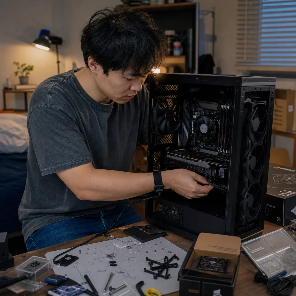
A side panel that refuses to close is often treated as a minor cable-management problem, but forcing it can put pressure on connectors and cable insulation. The better solution is to decide where each cable must turn before you start pushing the panel into place.
For a first build, prioritize the cables with the least flexibility: graphics-card power leads, motherboard power connectors, and any cable that exits a connector close to the panel. Give those cables a natural path, then fit the more forgiving fan, storage, and front-panel cables around them. A tidy-looking case is useful, but a relaxed cable path matters more than perfectly parallel bundles.
Identify the cables that need room
Not every cable bend creates the same risk. A thin front-panel lead can usually make a fairly tight turn without affecting the connector. A thick power cable may resist that turn, especially near its plug, where the individual wires are gathered into a larger sheath. The connector itself is also a rigid section, so the cable often needs room immediately after it exits the socket.
Start by looking at the case with both side panels removed. Find the narrowest areas between the motherboard tray, the case panel, and any raised features such as cable-routing channels. Then identify which connectors sit closest to the panel. A rear-mounted motherboard power socket, a graphics card near the side window, or a drive mounted behind the motherboard may each require a different routing strategy.
The cable’s natural direction is an important clue. If a connector points toward the front of the case, routing the cable straight forward before turning it toward the rear is usually easier than bending it sharply sideways at the socket. If the connector points toward the side panel, you may need more space above or below it, or a different cable path entirely.
Avoid planning around the cable’s appearance while ignoring its exit direction. A bundle that looks short and clean may be under more tension than a slightly longer route with a broad curve.
Leave a real bend radius
A cable doesn't need to form a perfect loop, but it should turn in a smooth curve rather than folding at one point. The bend radius is the approximate size of that curve: a larger radius creates a gentler bend, while a small radius produces a sharper one. You don’t need to calculate it precisely for most case work. Instead, look for signs that the cable is being asked to change direction too quickly.
If the outer sheath kinks, the plug tilts in its socket, or the cable springs back aggressively when released, the route is probably too tight. The same applies when a cable must be tied down immediately beside a connector to keep it from crossing the case. Fastening it there can transfer the pulling force directly to the socket.
Thick cables need more room than thin ones, and cables with multiple conductors in one sleeve may be especially stubborn. A sleeved extension can also make a power connection look neat while increasing the amount of material that must fit behind the panel. Plan for the complete cable assembly, including the connector housing, sleeve, combs, and any adapter—not just the wires shown in the case manual or product photograph.
A broad curve can take up more visible space, but it generally makes the side panel easier to install. If the panel has to be pressed firmly across a cable, the route isn't finished yet.
Check the high-power connection before closing up: If your graphics card uses a high-power connector or an adapter, follow the graphics-card and cable manufacturer’s instructions for seating and cable clearance. Confirm that the plug is fully inserted and that the cable isn't sharply bent right beside the connector.
Use routing space where it actually helps
Many cases include cable channels, rubber openings, tie-down points, and a gap behind the motherboard tray. These features are helpful only when they lead to a route with enough depth. A narrow channel can guide a cable without providing room for its full bend, particularly where several cables cross behind the tray.
Keep the thickest cables closest to the side panel’s deepest areas. Some cases have a raised center section behind the motherboard or extra space along the front edge. Use those areas for the 24-pin motherboard cable, graphics-card power cables, and other bulky runs. Put thinner cables in flatter areas or route them through separate openings.
Don’t assume that all of the space behind the motherboard tray is available. The panel may curve inward near its edges, and the side panel may have reinforcing ribs that reduce clearance. A route that fits in the middle can still prevent the panel from engaging along the top or front edge.
Before securing anything, place the panel near the case and check where it meets resistance. You don’t need to latch it or apply force. Hold it in its normal position and look for a cable that sits directly under an edge, seam, or raised section. That inspection can reveal a problem more safely than trying to close the case completely.
Change the connector’s approach before changing the cable
When a cable presses against the panel, the first adjustment should often be the direction in which it approaches the connector. Try routing it from above, below, or through the nearest opening rather than forcing the existing path to work. A cable that enters a socket in line with the connector usually needs less bending than one that arrives from the side.
This may require moving a cable behind the motherboard tray earlier than expected. For example, a graphics-card power lead can sometimes pass through a nearby opening and curve toward the card from a less crowded direction. The best route depends on the case layout, the position of the graphics card, and the length and flexibility of the particular cable.
If the connector is on a removable component, consider whether the component can be repositioned without compromising the build. A drive cage may block a cable’s natural path. A radiator, fan, or expansion card may occupy the exact area where a power lead needs to turn. Moving a cage or choosing another mounting position can create more useful room than bundling the cable more tightly.
Don't rotate or reposition a component in a way that leaves it unsupported, blocks a fan, interferes with another connector, or conflicts with the case manufacturer’s mounting options. Cable clearance is one part of the layout decision, not a reason to create a new mechanical problem.
Check the panel in stages
Install the cables and components, but leave the final ties loose until you’ve tested the side-panel fit. Once a bundle has been tightly fastened, changing one cable can require undoing several others. Temporary hook-and-loop straps or loose cable ties make it easier to adjust the route while the case is still open.
Fit the panel by aligning it with the case rather than pushing its center inward. Depending on the design, the panel may slide into a rail, hook onto tabs, or sit over a lip before it is secured. If it stops, remove it and find the point of resistance. Don’t use the panel screws to pull the panel against a cable; that turns the screws into a clamp.
Check both the side-panel fit and the connector side of the cable. A panel may close while still pressing the cable into a sharp case edge or tilting a plug. Look for cables that are pulled sideways, sharply creased, or visibly compressed. Check that no cable is touching a fan blade and that ventilation openings remain reasonably clear.
After the panel fits without force, open it once more and inspect the cables near their connectors. A cable that has shifted out of its socket or developed a tight kink during panel installation needs to be rerouted. It’s easier to correct this now than after the system has been moved or powered on.
When the available space is genuinely too small
Sometimes the problem isn't routing technique. The case may simply have less room behind the motherboard tray than the cable assembly requires. A side panel with a bulge or a deeper central channel can provide more useful clearance, while a flat glass panel may leave very little tolerance for thick wiring.
You can often improve the situation by removing unnecessary cable length from the crowded area. Route excess cable into a spacious lower compartment, behind a drive cage, or along a larger open section of the case instead of coiling it directly behind the panel. Keep the coil loose enough that it doesn’t push outward as the panel is installed.
Use only cables and extensions that are intended for the power supply and connection involved. Modular power-supply cables aren't universally interchangeable, even when their connectors appear similar. A replacement cable must be compatible with the specific power supply and rated for the intended component. Never solve a clearance problem by substituting an uncertain cable or forcing an adapter into an awkward position.
If the case still requires pressure to close, a different cable orientation, a supported extension, a component repositioning, or a different case may be the sensible choice. The small amount of time saved by forcing the panel isn't worth creating a strained connection that is difficult to inspect later.
A simple final check
Before powering on, confirm that every major power connector is fully seated, each cable leaves its connector without an abrupt fold, and no bundle is trapped between a panel and the case frame. Verify that the side panels close through their intended mechanism and that you didn’t use screws to overcome resistance.
Then focus on the cables that matter most: the motherboard power leads, graphics-card power connection, CPU power cable, and any adapter. Thin data and front-panel cables still deserve sensible routing, but the thickest and most heavily loaded connections should receive the most clearance.
A successful cable route is one that allows the panel to close naturally, leaves connectors aligned, and keeps cables away from moving fans and sharp edges. Start with connector orientation and the thickest cables, use the case’s deepest routing areas, and postpone tight bundling until you’ve tested the panel. That approach usually produces a cleaner build with less strain and fewer surprises when the system needs maintenance later.