How to Replace a Motherboard Without Losing Track of Front-Panel Connections
I’ll compare the safest ways to document front-panel wiring, move components, and reconnect a case during a motherboard replacement so you can avoid wasted troubleshooting and reuse parts that still work.
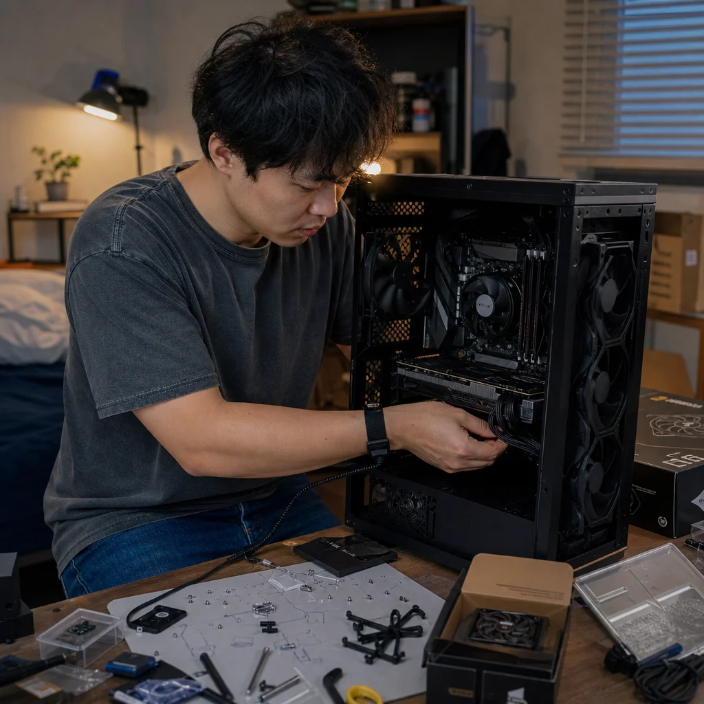
Replacing a motherboard is usually straightforward until the case’s small front-panel wires become a mystery. Power-switch, reset, activity-light, USB, and audio connectors may all be routed together, while motherboard headers can move or change between generations. Losing track of one connection can leave a working system that appears completely dead—or a front USB port that never functions.
The most cost-efficient approach is to treat the old motherboard as a wiring map before removing anything. You don’t need to replace the case, buy a special cable kit, or guess at every connection. You need clear documentation, a compatible replacement board, and a deliberate order of operations.
Document the old connections before removing the board
Shut the computer down normally, switch off the power supply, unplug the power cable, and press the case’s power button once to discharge obvious residual power. Move the system to a well-lit workspace where you can reach both sides of the case. If the case has a removable right-side panel, take it off; cable routing is much easier to understand when you can see where each lead originates.
Take several photos before disconnecting anything. Include one wide image showing the motherboard’s overall layout, followed by close-ups of the lower-right corner, lower-left corner, and any headers along the board’s edge. A photo should show both the connector and the printed labels around it. If a cable blocks the label, move the cable gently and take another image rather than relying on memory.
Write down each connection in plain language. For example, “case power switch to lower-right two-pin header” is more useful than “small black plug near bottom.” Record the connector’s orientation where polarity matters. Power and reset switches normally work in either orientation, but power and drive LEDs don't; their positive and negative leads must be placed correctly.
A simple paper diagram is often faster than repeatedly zooming into phone photos. Sketch the old board as a rectangle, mark the header location, and note the cable label and pin direction. You can also label loose cables with small pieces of painter’s tape. Avoid adhesive labels that leave residue inside the case or obscure a connector’s printed markings.
Confirm the new board’s layout: Before you move any wires, compare the replacement motherboard manual with your photos. Header names and positions vary, and the manual is the authoritative source for the board you’re installing.
Separate front-panel connections by function
The small front-panel connectors are the easiest to confuse because they often look similar and may be bundled together. Separate them into three groups: switches and indicator lights, internal USB connections, and front audio.
The power-switch and reset-switch leads are usually two-wire connectors labeled POWER SW and RESET SW, or similar. They connect to individual pairs of pins in a front-panel header, often labeled F_PANEL, PANEL, or JFP1. The motherboard manual may show a diagram with several pairs in one block. Don’t assume the layout matches your previous board, even if both boards use a similar header shape.
Power and drive-activity LEDs also use two-wire connectors. These are polarity-sensitive, so look for a small positive symbol, colored wire, or + marking on the connector. If an LED doesn’t illuminate after the first boot, shut the system down and reverse that connector rather than treating the problem as a failed motherboard. The PC can operate normally with an indicator LED connected backward.
Front USB cables are larger and keyed. A USB 2.0 cable commonly connects to a nine-pin internal header with one missing position, while USB 3.x front-panel cables are wider and may use a bulky keyed connector. Newer cases can also include a USB Type-C front-panel cable that requires a compatible internal header. These connectors generally shouldn't be forced. If the replacement board lacks the required header, the port may remain unused unless an appropriate expansion solution is available.
The front-audio cable is commonly labeled HD AUDIO and normally connects to a keyed header near the lower-left edge of the board. Some cases include an older AC’97 plug on the same cable, but that doesn’t mean it should be used with a modern board. Follow the motherboard and case documentation, and connect the header intended for the audio standard supported by the system.
Plan the motherboard swap around the connections
Before removing the old board, disconnect the external cables, graphics card, storage data cables, and internal power connections. Remove the graphics card and other expansion cards before loosening the motherboard. Disconnect the CPU cooler fan cable, case fans connected directly to the board, and any pump or lighting cables that would prevent the board from lifting out.
The front-panel leads can be disconnected early, but leave them visibly grouped until you’ve recorded their destinations. If several cables are tightly packed, separate them one at a time and place them where you can identify them. Don't pull on the wires themselves; grip the plastic connector. A damaged crimp or partially pulled wire can create an intermittent problem that looks like a bad header.
Check the case’s motherboard standoffs before installing the replacement board. The new motherboard’s form factor may be the same as the old one, but mounting-hole patterns and included accessories can still differ. A misplaced standoff under the board can cause electrical problems, so remove any standoff that doesn’t align with a mounting hole. Also confirm that the rear I/O shield is installed if the replacement board uses a separate shield; it’s much harder to fit after the board is mounted.
Install the board without trapping front-panel cables underneath it. Route the small leads around the board’s edge, leaving enough slack to reach the new header without pulling sideways on the connector. If the header is in a different location, use the case’s cable-routing openings rather than stretching a wire across the board. Keeping the wiring close to the case perimeter improves airflow and makes a later repair easier.
Reconnect in an order that limits confusion
Once the motherboard is secured, connect the large power cables first. The 24-pin motherboard connector and the CPU power connector are essential, but they aren't interchangeable. The CPU power lead generally routes to a socket near the top edge of the board, while the 24-pin connector fits along the right edge. Press each one firmly until its latch engages.
Install the processor cooler and connect its fan or pump to the header specified by the motherboard manual. Then install memory, graphics, and storage as appropriate for the platform. Keep the number of loose connections manageable: reconnecting every fan, drive, and lighting accessory at once makes it harder to identify the source of a problem.
Reconnect the case connections by category. Start with the front-panel switch and LED leads, then attach front USB, front audio, and case fans. Refer to the new board’s diagram for every small connector. A front-panel plug that physically fits somewhere nearby may still be on the wrong pins, and a keyed connector should never be forced to overcome a mismatch.
For the power and reset switches, orientation usually doesn’t matter. For LEDs, match positive to positive and negative to negative. Some cases combine several switch or LED leads into a single block, while others provide separate two-pin plugs. If the case includes a one-piece block and the board expects individual connectors, check whether the block can be separated or whether the case provides an adapter.
Test the system before closing the case
Before reinstalling both side panels, perform a controlled first-boot check. Connect the monitor, keyboard, and power cable, then switch on the power supply and press the case power button. Watch for fans, diagnostic lights, display output, and any motherboard error codes. Don’t repeatedly press the power button if nothing happens; switch the power supply off and review the power and front-panel connections.
A completely unresponsive system often points to the front-panel power-switch connection, the power supply switch, the 24-pin cable, or the CPU power cable. You can briefly test whether the case switch is the problem by using the motherboard’s documented power-switch pins, but only if the manual clearly identifies them. Use the tip of a screwdriver to momentarily bridge the two specified pins; don’t sweep across the header or guess at the location.
If the system starts but doesn’t display an image, the issue may be memory seating, graphics installation, CPU support, or firmware compatibility rather than front-panel wiring. Check the board’s diagnostic indicators and consult its manual. A replacement motherboard may require a firmware version that supports the installed processor, and that compatibility detail can vary by exact board revision and CPU model.
After reaching the firmware setup screen, verify that the system detects the expected memory and storage. Test the case power button, reset button, power LED, and drive-activity LED individually. Plug a known-good device into each front USB port, and check front audio after the operating system loads. If a switch works but an LED doesn't, reverse the LED connector. If a USB or audio port fails, power down and inspect that cable and header rather than assuming the entire case is incompatible.
Check platform-specific support: Before final assembly, verify the replacement board’s CPU support, memory type, firmware requirements, and internal header availability against the exact parts in your system. These details can differ between otherwise similar models.
When an old case connection doesn’t fit
A motherboard replacement can expose limitations in an older case without making the case unusable. The power switch and reset switch are generally simple contacts, so they can often continue working with a different board layout. Front USB and USB Type-C support is more dependent on the headers present on the new board. You may have to leave a port disconnected, use a compatible adapter, or add a PCIe expansion card if the feature is worth the cost and available space.
Be cautious with improvised adapters. A connector that changes physical shape isn't automatically electrically compatible. Check the pinout, not just the plug’s appearance, and avoid forcing a cable into a header with a different keying arrangement. The cheapest solution is often to leave one nonessential port unused rather than risk damaging the board or case wiring.
If your case has proprietary front-panel wiring, document it especially carefully before removal. Some prebuilt systems use combined connectors, unusual pin assignments, or integrated lighting and controller cables. The replacement motherboard may support the standard functions but not every proprietary feature. Separating what you need for basic power from what is optional helps you avoid replacing functioning hardware unnecessarily.
Finish the installation methodically
Once the first boot succeeds and the front-panel functions have been tested, shut the system down and disconnect power before making final cable adjustments. Route cables behind the motherboard tray, secure them without crushing or sharply bending connectors, and confirm that no wire can touch a fan blade. Reinstall the expansion-card brackets and side panels only after checking that the graphics card and other cards are fully seated.
Keep your photos and notes for the next upgrade. Add a short record of which case ports work, which remain unused, and where the motherboard manual is stored. That documentation costs nothing, saves time during troubleshooting, and is more useful than trying to remember the arrangement months later.
The reliable method is simple: photograph the old board, label the cables, compare the new manual, reconnect by function, and test before closing the case. Spending a few extra minutes on front-panel documentation protects the parts you already own and turns a potentially confusing motherboard swap into a controlled hardware change.