Fit a Radiator, Tall Memory, and Top Exhaust in One Case
I’ll help you map the radiator, fan, memory, and motherboard clearances that determine whether a top-mounted cooling layout will actually install cleanly, rather than merely appear compatible in a case specification.
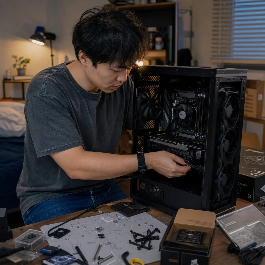
A case can list support for a top radiator, your motherboard can accept tall memory, and the cooler can be advertised as a slim assembly—yet the parts may still compete for the same narrow strip of space. The problem is usually not a missing compatibility feature. It’s overlapping clearances.
When you want a top radiator, tall memory, and top exhaust in one case, the useful question isn’t simply “Does the case support a 360 mm radiator?” You need to map the entire stack: the case roof, radiator, fans, motherboard components, memory modules, and the clearance above the board. A small amount of planning can prevent discovering the conflict after the motherboard is installed and the tubing is already routed.
Start with the vertical stack
A top-mounted radiator and its fans occupy space between the case roof and the motherboard. Think of that area as a stack of layers rather than as one component:
- The case’s mounting bracket or roof clearance
- The radiator thickness
- The fan thickness
- Any offset between the roof and motherboard
- The motherboard’s tallest components near the top edge
- The memory modules and their heat spreaders
A common radiator is around 27 to 30 mm thick, while a standard case fan is often 25 mm thick. Together, that can consume roughly 52 to 55 mm before you account for the case bracket, screws, washers, cable heads, or any extra spacing. Thicker radiators and push-pull fan arrangements increase the stack quickly.
The most important measurement isn't the case’s maximum radiator length. It is the available distance from the radiator-and-fan assembly down to the nearest obstruction on your motherboard. That obstruction might be the top edge of a memory module, the motherboard’s upper heatsink, a reinforced power-delivery cover, or an EPS power connector and its cable.
Measure the motherboard’s danger zone
Top clearance problems usually occur along the upper edge of the motherboard, especially around the first memory slot and the CPU socket. Tall memory is often the obvious obstruction, but it may not be the tallest one. The motherboard’s VRM heatsink can extend sideways or upward, and its decorative cover may sit directly beneath the radiator fans.
Look at the motherboard layout with the case’s top mounting area in mind. Identify the nearest points where the top radiator assembly could meet the board. Measure from the motherboard mounting surface to the top of the memory modules, then separately measure to the highest part of the VRM heatsink. Don't treat the top edge of the PCB as the clearance limit; the components above it are what matter.
Memory height is measured from the bottom edge of the module to its highest point. If a kit has a large heat spreader, light bar, or other raised feature, use that maximum height. A module that is only a few millimeters taller than another can change whether the fan frame clears the board.
You’ll also want to check whether the first memory slot is unusually close to the CPU socket. Some boards leave more room around the socket, while others place the DIMM slots close enough that a fan frame can overlap them even when the memory itself would fit beneath the radiator.
Compare the real assembly, not separate specifications
A case specification may state that it supports a top radiator and a certain motherboard size. A memory specification may list the module height. Those facts are useful, but they don’t automatically describe the assembled relationship between the parts.
For a basic top exhaust layout, calculate the approximate assembly depth like this:
radiator thickness + fan thickness + mounting or bracket allowance
Then compare that depth with the case’s stated top clearance above the motherboard. If the numbers are close, assume the fit is conditional rather than guaranteed. Manufacturer measurements may use different reference points, and a listed clearance may not include the fan frame, screw heads, or motherboard components.
For example, a 30 mm radiator paired with 25 mm fans creates a 55 mm core stack. If the case provides 58 mm of nominal clearance, the theoretical margin is only 3 mm. That margin can disappear because of the top bracket’s shape, a raised motherboard heatsink, a slightly offset radiator, or the need to route an EPS cable beneath the fan frame. A nominal fit with almost no margin is difficult to install and harder to maintain.
Confirm the tightest gap: Before buying or installing the parts, find the case’s radiator-to-motherboard clearance drawing or measure the actual mounting positions. Compare it with the full radiator-plus-fan thickness and the height of your motherboard’s memory and VRM areas, not just the supported radiator size.
Understand offset and mounting positions
Top radiator brackets can make the difference between a clean fit and a blocked memory slot. A bracket that offsets the radiator toward the side panel may clear the memory while moving closer to the motherboard’s upper heatsink or the EPS connector. An offset toward the front or rear can create a different conflict with the CPU socket, rear I/O shroud, or front-panel hardware.
If the case uses elongated mounting slots, don’t assume every position is equally useful. A radiator may fit only when shifted away from the memory, and that position may depend on the motherboard’s width and the number of fan positions supported. A long radiator can also span several mounting zones, meaning the front fan might clear the memory while the rear fan collides with the VRM heatsink.
The practical approach is to map the assembly in two dimensions. From the side, check the vertical stack above the motherboard. From above, check where the radiator and fan frames sit relative to the DIMM slots, socket, heatsinks, and cable connectors. A side-view measurement alone can miss a horizontal overlap.
Check the fan frame, not only the blades
Builders often compare the radiator thickness with memory height and forget that the fan frame is wider than the fan blades. The frame may extend over the edge of the motherboard even when the center of the fan isn't above a memory slot.
The rear fan position deserves particular attention. It can overlap the CPU socket area or the upper VRM heatsink, while the front fan may sit above the memory slots. With a 360 mm radiator, the full length often covers the CPU area and much of the board’s upper edge. With a 240 mm radiator, the mounting position may leave more options, but that depends on the case bracket and motherboard layout.
Fan thickness also varies. A slim fan can recover some clearance, but it may have different acoustic or airflow characteristics, and the case may not provide enough room for its mounting screws. A thicker fan can improve airflow in some situations but consumes the exact space you need to clear tall memory. Treat any substitute fan as a new fit calculation rather than a guaranteed fix.
Decide which constraint matters most
The minimalist solution is usually to avoid stacking more hardware than the case and motherboard layout can comfortably support. A single row of fans on one side of a radiator is simpler than push-pull. A radiator with a conventional thickness is easier to place than an unusually thick model. Memory with moderate-height heat spreaders gives you more motherboard and cooler options than oversized modules.
You may also be able to change the layout rather than the components. Moving the radiator to the front can remove the top-memory conflict, though it changes airflow and may affect graphics-card clearance. Using the radiator as a top exhaust often gives the graphics card a less restricted intake path, but it makes the motherboard’s upper edge the critical clearance zone.
If you’re choosing between tall memory and a particular top radiator, compare the value of the feature that creates the conflict. Decorative memory height rarely improves compatibility, while a quieter or better-positioned cooling layout may matter every day. Likewise, an oversized radiator may offer little practical benefit if a smaller unit or a well-sized air cooler can handle the processor without consuming the case’s most limited space.
Plan the installation order
Even when the parts fit, installation order affects whether the build is pleasant or frustrating. Install the CPU, memory, M.2 devices, and the CPU power cable while the motherboard is outside the case whenever possible. If the radiator and fans will sit close to the top edge, test-fit the motherboard before permanently tightening the radiator assembly.
A useful sequence is to mount the fans to the radiator, place the assembly in the intended top position without fully tightening it, and then lower the motherboard into the case. Check the memory slots, VRM heatsink, CPU power connector, and top fan screws. If the assembly needs to slide toward one side, confirm that the final position still leaves room for the side panel and cable routing.
Don't force the motherboard beneath a fan frame or tighten the radiator while it is pressing against a heatsink. Contact can damage a component, deform a fan frame, or make later removal needlessly difficult. If the fit depends on flexing the board or compressing a cable, it isn’t a useful clearance margin.
Build in room for maintenance
A layout that installs with one millimeter to spare may work initially but become inconvenient when you replace memory, clean dust, or reconnect the CPU power cable. You should be able to remove a memory module without removing the radiator, and ideally you should be able to reach the relevant motherboard screws and connectors without dismantling the cooling assembly.
Leave room for the fan cable to exit without crossing the blades or being pinched against the frame. Check that the radiator’s tubes can bend without sharp kinks and that their connection point doesn’t press against the memory or motherboard heatsink. On an all-in-one liquid cooler, the tube orientation may limit which end of the radiator can sit toward the front or rear.
The best fit isn't the one that technically accepts every part. It’s the one with a visible margin, a sensible installation sequence, and enough access to service the system later. If the only way to make the layout work is to use a thinner fan, shift a bracket to an extreme position, and route cables through a narrow gap, consider that a warning rather than a clever optimization.
Before you commit, write down four numbers: the radiator thickness, fan thickness, available case clearance, and tallest obstruction on the motherboard. Then check the horizontal position of the fan frame and the cable connectors. If the resulting margin is comfortable, the top-exhaust layout should be straightforward. If it is marginal, the simplest fix is usually to reduce the stack, choose shorter memory, use a different bracket position, or move the radiator to another mounting location.