What to Check When a Motherboard Has More M.2 Slots Than CPU Lanes
When a board offers more M.2 sockets than the processor can connect directly, I’ll show you how to trace chipset lanes, shared bandwidth, and disabled ports so you can choose storage locations without guessing about performance.
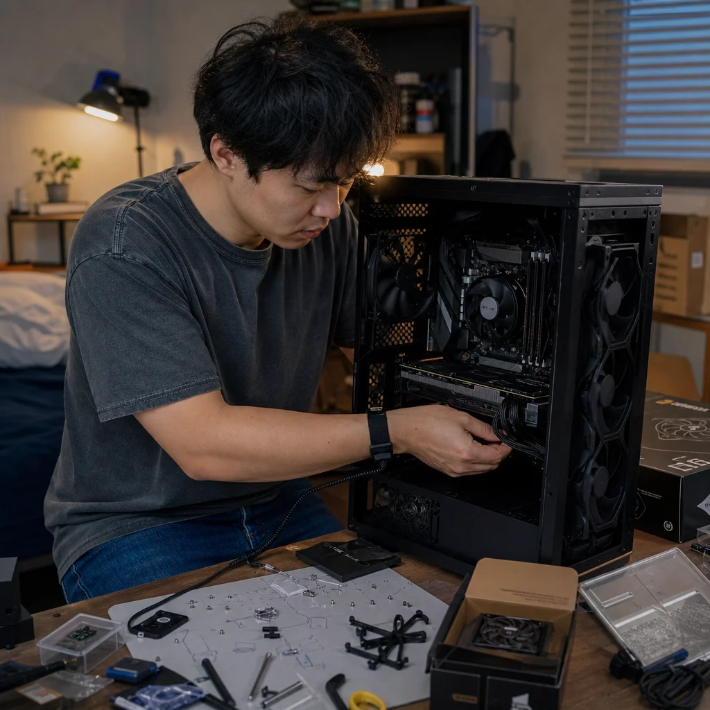
A motherboard can advertise three, four, or even more M.2 sockets while the processor provides only enough direct PCIe lanes for one or two NVMe drives. That isn’t necessarily a problem. The extra sockets usually connect through the motherboard chipset, which has its own pool of PCIe lanes and a shared link back to the CPU.
The important question isn’t simply how many M.2 slots the board has. It’s where each slot gets its lanes, what else shares them, and whether your planned workload can saturate the connection.
Start with the lane map, not the socket count
An M.2 socket is a physical connector and mounting point. It doesn’t, by itself, tell you whether the installed drive communicates directly with the processor or travels through the chipset. Most modern NVMe sockets use four PCIe lanes, commonly called PCIe x4, but those lanes can come from different places.
A CPU-connected M.2 slot has a relatively direct path to the processor’s PCIe controller. On many desktop platforms, one socket—often labeled something like M2_1, M.2_1, or CPU_M.2—gets four lanes from the CPU. The remaining sockets may be supplied by chipset lanes. Some high-end platforms provide more processor lanes and may connect multiple M.2 sockets directly, but you should confirm that from the specific board and processor documentation rather than infer it from the socket count.
The processor’s total PCIe lane budget also serves other devices. A graphics-card slot may consume sixteen lanes, additional expansion slots may use four or fewer, and an onboard M.2 socket may use another four. A board can expose many connectors while still having to divide or reroute those resources when particular slots are populated.
The chipset adds flexibility, but it doesn’t create a second unlimited connection to the CPU. Its devices communicate with the processor through a chipset uplink. That link also carries traffic from chipset-connected M.2 drives, SATA ports, USB controllers, networking, audio, and other peripherals. Several fast devices can therefore compete for the same upstream bandwidth even when each individual M.2 socket is labeled PCIe x4.
What the motherboard manual should tell you
Look for three kinds of information in the manual or the board’s block diagram.
First, identify the lane source for each M.2 socket. The diagram may show a socket connected to the CPU and others connected to the chipset. It may also identify supported link widths and generations, such as PCIe 5.0 x4 or PCIe 4.0 x4. A socket’s maximum specification describes what it can support, not necessarily what every installed drive will receive in every configuration.
Second, find the sharing rules. A socket may disable one or more SATA ports when populated. An expansion slot may drop from x4 to x2, become unavailable, or share lanes with another M.2 socket. On some boards, using a particular M.2 slot changes the graphics slot’s operating mode. These arrangements differ substantially between models, including boards built around the same chipset.
Third, check whether the restrictions apply to link generation, lane width, or device availability. “M.2 shares bandwidth with SATA” could mean a SATA port is disabled. “PCIEX16_2 shares bandwidth with M.2_2” could mean one connector is disabled, or that both remain available at a reduced width. The exact wording matters.
Trace your board’s connections: Before installing drives, open the motherboard manual’s block diagram and storage table. Record each M.2 socket’s lane source, supported PCIe mode, shared connectors, and any condition that disables or reduces another slot.
Board firmware can also expose useful information after installation. The BIOS or UEFI may show whether a slot is running at x4, x2, or another width, and diagnostic tools in the operating system can report the negotiated PCIe generation and width. These readings describe the current link, while the manual explains the board’s possible configurations.
Understand the difference between direct and chipset-connected storage
A CPU-connected NVMe drive generally has the cleanest path to the processor and memory subsystem. It avoids sharing the chipset uplink with other chipset devices, which can be useful for a busy scratch drive, demanding project files, virtual machines, or workloads that move data continuously between storage and the rest of the system.
A chipset-connected drive isn't automatically slow. It may still operate at its full advertised PCIe width when considered by itself. If the chipset link has enough capacity for the active traffic, everyday application loading, game storage, and many workstation tasks will show little practical difference between the two locations.
The limitation appears when several chipset devices are active at once. Two or more NVMe drives can contend for the uplink, especially during simultaneous transfers. A fast network connection, USB storage, capture device, or other high-throughput peripheral can add to that contention. The drives may each retain a PCIe x4 connection locally, but their combined traffic still has to cross the shared route to the CPU.
This is why theoretical SSD benchmarks can be misleading. A sequential test that runs against one drive may show the expected result, while a workload involving two drives, a network backup, and a USB device may behave differently. Random access, queue depth, latency, and the application’s ability to parallelize work can matter more than the maximum sequential number printed on the drive’s box.
Match the fastest path to the busiest workload
Use the CPU-connected M.2 socket for the drive whose traffic most needs a direct path. That might be a system drive in a latency-sensitive workstation, a scratch drive used alongside another active storage volume, or a project drive that feeds sustained data to the CPU and graphics card. There isn’t one universal priority, but putting the most demanding independent workload on the least shared path is a sensible default.
Chipset-connected sockets are often good locations for secondary game libraries, less active project archives, backups, and additional capacity. They can also be appropriate for a second drive when the system rarely accesses both drives heavily at the same time. Capacity and cooling may outweigh a small path-level advantage in these roles.
If you plan to use multiple high-end NVMe drives, consider the whole platform rather than trying to make every drive CPU-connected. The processor may not have enough direct lanes without reducing graphics-slot bandwidth or using a platform with more available lanes. In some systems, a PCIe expansion card with multiple M.2 drives may require lane bifurcation support from the CPU and motherboard. Without the correct bifurcation support, the card may expose only one drive or fail to operate as intended.
An add-in card can also occupy an expansion slot that shares resources with onboard M.2 sockets. The board’s slot wiring, not the card’s marketing specification, determines the result. Check whether the slot is electrically x16, x8, or x4, whether it connects to the CPU or chipset, and whether the firmware supports the required split configuration.
Watch for less obvious M.2 restrictions
Not every M.2 connector is intended for the same type of device. A socket may support NVMe PCIe drives but not SATA M.2 drives, or it may support both while sharing its controller with conventional SATA ports. Keying, socket length, and mounting positions confirm physical compatibility; they don’t establish electrical compatibility.
Some boards support different PCIe generations depending on the processor installed. A socket may be physically capable of a newer generation but operate at an older one with a particular CPU, or it may fall back because of firmware settings, signal integrity limits, or the installed drive. PCIe is generally backward compatible, but the negotiated speed is limited by the weakest supported component in the connection.
Thermal behavior matters too. A drive under a graphics card or beneath a motherboard heatsink may be on a convenient CPU-connected slot but run hotter than a secondary drive elsewhere. Sustained workloads can trigger thermal throttling, erasing the advantage of the supposedly faster location. Make sure the drive’s heatsink makes proper contact, and don’t stack a motherboard cover on top of a drive’s own heatsink unless the board and drive are designed for that arrangement.
Confirm the installed configuration: After the first boot, check the drive’s negotiated PCIe generation and lane width in your firmware or a trusted hardware-information utility. If the result is lower than expected, compare it with the manual’s sharing table before changing settings or moving hardware.
A simple way to plan several drives
Begin by listing the drives and devices you expect to use at the same time. Note which storage volume will host the operating system, which will handle active projects or scratch data, and which will mainly hold games or less frequently accessed files. Add high-bandwidth devices such as a discrete graphics card, fast wired networking, capture hardware, and external storage.
Next, mark the board’s CPU-connected and chipset-connected paths. Assign the busiest storage workload to the direct path, then distribute the remaining drives across available chipset sockets while avoiding known conflicts. If a slot disables SATA ports you need, choose another socket or revise the storage plan before assembly.
Finally, validate the result with the actual workload rather than assuming that more M.2 drives will always improve performance. A single fast drive can be enough for a general-purpose system. Additional drives are most useful when they provide more capacity, isolate workloads, simplify backups, or allow applications to read and write independently. Filling every socket can add heat, configuration constraints, and shared traffic without adding a noticeable benefit.
The minimalist answer is to treat the CPU-connected M.2 slot as a limited resource, not as a prize that every drive must claim. Put the drive with the strongest reason to avoid shared chipset traffic there, use the other sockets according to the manual’s lane map, and confirm the negotiated links once the system is running. That approach gives you the important performance and compatibility information without turning the motherboard’s connector count into a guessing game.