How to Photograph and Label a Build for Easier Future Repairs
I’ll show you how to photograph cable routes, label hardware, and record firmware settings before a repair turns your well-organized build into a guessing game. You’ll create a small, durable reference that remains useful long after the original assembly is forgotten.
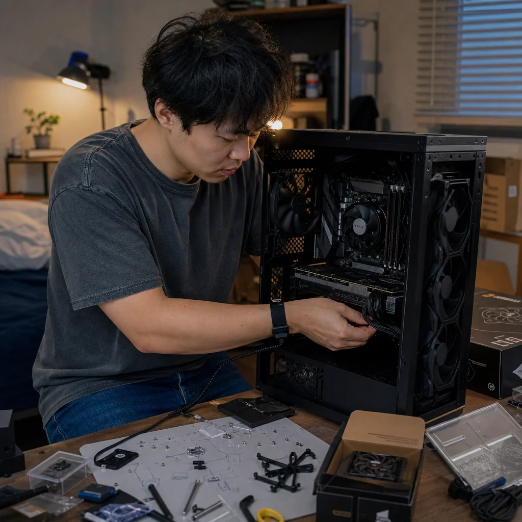
A repair is much easier when you can see how the system was arranged before you touched it. Without that record, a disconnected front-panel lead, unfamiliar power cable, or changed firmware setting can turn a straightforward job into a memory test.
The goal isn’t to document every screw. It’s to create a compact reference that answers three questions: what is this part, where does it connect, and what was different before the repair? A few well-planned photographs, readable labels, and a short change log can preserve those answers for years.
Photograph the build before you change anything
Take the first set of photographs while the computer is complete and working. Photographing after you remove a graphics card or pull cables free defeats much of the purpose, because the original routing and connections are often the details you’ll need later.
Start with the computer powered down. Remove the side panel if it blocks the view, and use enough light to distinguish cable ends and connectors. Keep the camera level where possible, and take both wide views and close-ups. A wide photograph shows the overall layout; a close-up shows which connector is attached to which header or device.
Useful views usually include:
- The interior from the motherboard side, showing major components and cable routes.
- The rear of the motherboard tray, where power and data cables may be bundled or crossed.
- The motherboard’s lower edge, including front-panel, USB, audio, fan, and lighting headers.
- The area around storage drives and graphics-card power connectors.
- The power supply modular sockets and the cables attached to them.
- The outside of the case, including front-panel controls and any unusual accessories.
Take an additional photograph whenever a cable disappears behind the motherboard tray or splits into more than one connector. The picture should make the path understandable, not merely prove that a cable exists. If a cable is difficult to trace, photograph it at both ends and include a nearby component or case feature as a visual landmark.
Avoid relying on a single photograph taken from across the room. Small connector markings may be unreadable, and a large cooler or graphics card can hide the header you’re trying to identify. Move closer, keep the image sharp, and retake any photograph where the connector labels are obscured by glare or shadow.
Use labels that survive disassembly
Labels are most useful when they identify both the destination and the purpose of a connection. “Cable 1” tells you very little. “CPU_FAN to top-right motherboard header” is much more useful, especially if you’re looking at the label months later with a cooler or graphics card removed.
You don’t need to label every cable permanently. Short paper flags, removable cable labels, or small pieces of low-residue tape can identify connections that are likely to be disturbed during maintenance. Place the label near the connector, but not so close that it prevents the latch from releasing or covers a connector marking.
For permanent or semi-permanent identification, label the cable rather than the socket when the cable may be replaced. A label on a modular power-supply cable can say “GPU power” or “CPU/EPS,” while your records can separately note the exact socket used on the power supply. Don't assume that modular power cables are interchangeable between power-supply models or brands; retain the cable with the unit it belongs to and record that relationship clearly.
For small motherboard headers, a paired naming system works well. Mark the cable as “PWR SW,” “RESET SW,” “HDD LED,” or “PWR LED,” then record the header location in your notes. The labels printed on motherboard headers vary, and some are difficult to read after the system is installed. A photograph with the board’s printed markings visible gives you a second source of information.
If you use several similar fans, label them by position rather than by an arbitrary number: “rear exhaust,” “top-front intake,” or “CPU cooler fan.” Position-based names remain meaningful when you remove and reinstall a fan. If airflow direction matters to your layout, record whether each fan is intended as intake or exhaust rather than relying on memory.
Build a simple visual record
Create a folder for the computer and keep the original photographs together. A useful naming scheme includes the date and subject, such as 2025-03-08-motherboard-lower-headers.jpg or 2025-03-08-power-supply-cables.jpg. The exact format matters less than using it consistently and making the names understandable without opening every file.
Add a one-page text document or note with the main component identifiers. Include the motherboard model and revision if it is printed on the board, the processor, graphics card, memory kit, storage devices, power supply model, case, and cooling hardware. You don’t need a full inventory of every screw, but you should record anything whose replacement or compatibility could matter later.
Serial numbers can help with warranty or support questions, but handle them carefully. Store them in a private location rather than posting them with public photographs. A photograph of a product label can be useful for your own records, but crop or obscure serial numbers before sharing images online.
A small diagram can clarify what photographs can't. Draw the motherboard as a simple rectangle and mark the CPU fan header, system-fan headers, storage connections, front-panel header, and any unusual adapters. This doesn’t need to look like an engineering drawing. Its purpose is to give you a quick map when the case is open and the original view is no longer available.
Check your reference while the system is intact: Open the photographs on a larger screen and confirm that connector names, cable ends, and hidden routes are actually readable. Retake unclear images now, while every connection is still available to inspect.
Record firmware and software settings separately
Physical photographs won’t preserve settings that exist only in firmware or software. Before changing hardware, record the settings you would otherwise have to reconstruct. This is especially useful when replacing a drive, resetting a motherboard, updating firmware, or troubleshooting an unstable system.
For firmware, take screenshots if the interface supports them, or photograph the relevant screens. Record settings such as the boot order, memory profile, fan-control mode, storage mode, virtualization setting, and any manually selected power or performance options. Use the motherboard’s exact terminology where possible. “Fast memory enabled” is less useful than the profile name or setting shown on the screen.
Also record the firmware version and the date of the record. Firmware menus and setting names can differ between manufacturers and board revisions, so your notes should preserve what your particular system displayed rather than using a generic checklist as a substitute.
Verify settings against your own hardware: Before restoring a firmware setting, compare your notes with the current motherboard manual and the values shown on screen. Firmware updates and component changes can alter available options, defaults, or recommended settings.
For the operating system, note drive-letter assignments, storage-pool arrangements, special fan-control software, backup tools, and applications that control lighting or other hardware. If a repair requires reinstalling software, these notes can help you distinguish a missing utility from a hardware fault.
Make a change log, not just a starting snapshot
A starting snapshot tells you how the build looked originally. A change log explains how it got there. Keep entries short but specific: date, change, reason, parts affected, and result.
For example, an entry might say that a rear fan was moved from a motherboard header to a powered hub because the header reported an unstable speed, or that a second storage drive was added to a particular SATA port and appeared under a certain operating-system volume name. These details can explain behavior that otherwise looks mysterious during a later repair.
Record temporary changes too. If you disconnect a graphics-card support bracket, move a fan to reach a connector, or test the computer with one memory module removed, write that down and update the record when the original arrangement is restored. Temporary troubleshooting changes are easy to forget, and forgotten changes can become the next repair problem.
When you replace a part, note what happened to the old one. Write down whether it was discarded, stored as a spare, returned under warranty, or installed in another computer. If the replacement has a different model or capacity, record that distinction rather than simply writing “new drive” or “new RAM.”
Store the information where you can reach it
Keep one copy with your normal maintenance files and another copy somewhere accessible if the computer can't start. An encrypted cloud folder, external drive, or home server can work, provided you can retrieve the files without relying on the computer being repaired. For a particularly important system, a printed one-page connection map kept with spare parts is also worthwhile.
Use ordinary file formats for the durable parts of the record. JPEG or PNG photographs and plain text or PDF notes are easier to open in the future than files tied to a single note-taking application. If your storage system automatically compresses or renames images, make sure the resulting files remain clear and logically organized.
Review the record after major upgrades. Add new photographs when cable routes change, remove notes that no longer describe the machine, and mark replaced components as retired rather than silently deleting their history. You don’t need to rebuild the entire archive after every small adjustment; update the sections that changed.
A repeatable repair-day routine
Before opening the case, shut the system down normally, disconnect external power, and give yourself enough light to identify connectors without pulling on them. Photograph the intact build, then photograph each area immediately before you disturb it. If a connection is unclear, stop and capture a closer view instead of trusting a quick glance.
As you remove parts, place screws and small adapters in labeled containers or bags. Pair the labels with your photographs: “GPU bracket,” “front-panel screws,” and “M.2 heatsink” are more useful than one container marked “computer parts.” When you finish, photograph the repaired arrangement and add a short entry describing what changed and whether the original problem was resolved.
The best documentation isn't the most detailed archive. It’s the record you can understand quickly when the case is open, the system is inconveniently disassembled, and the original builder’s memory has moved on. Clear views, destination-based labels, firmware notes, and a simple change log give you enough context to repair the computer without turning every future service session into detective work.