Check Whether a Case Front USB Port Matches the Motherboard Header
I’ll compare the internal USB header types found on motherboards, explain how front-panel cables are keyed and limited, and show you safe, cost-conscious alternatives when a case port doesn’t have a matching connection.
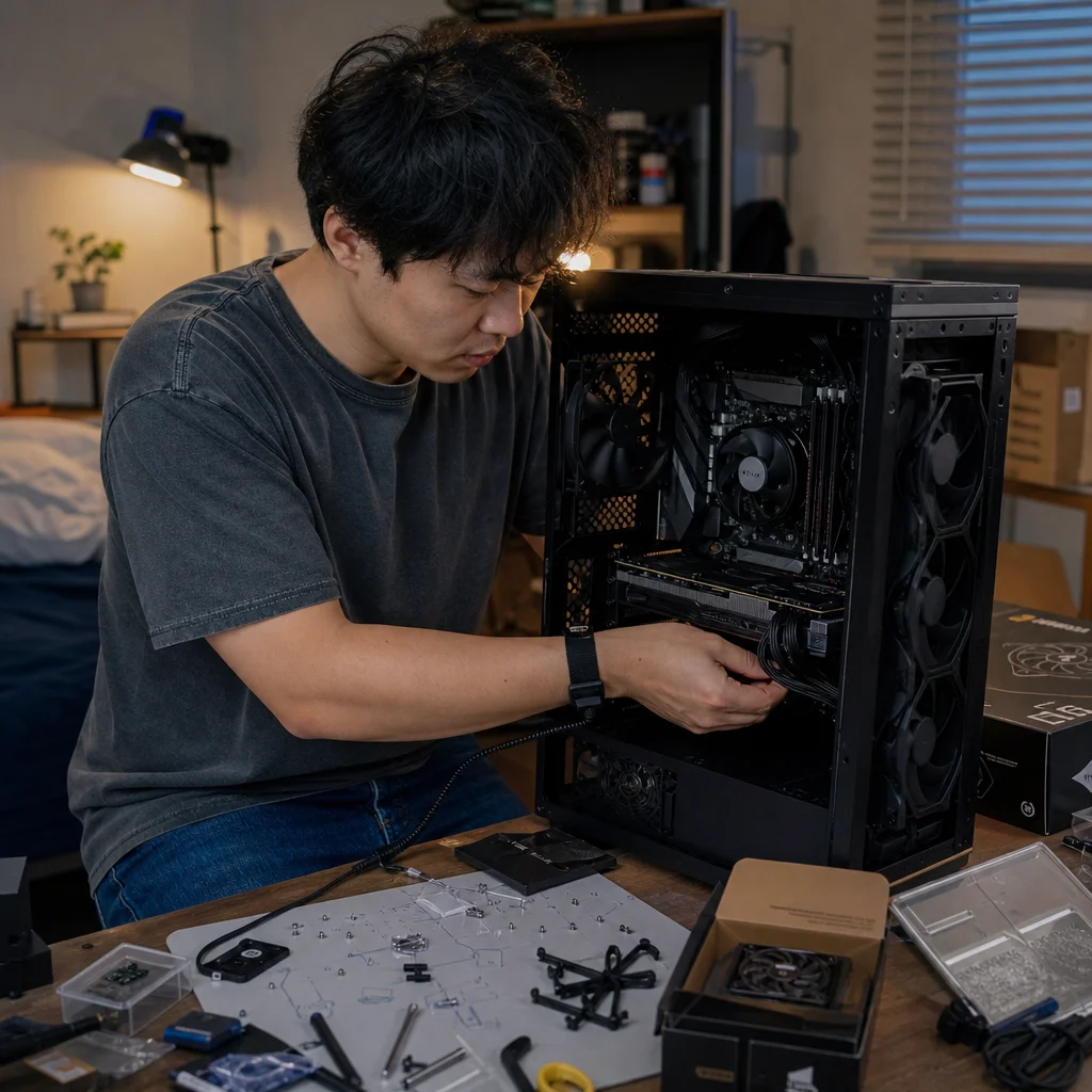
A front USB port can look ready to use while its cable ends in a connector your motherboard doesn’t support. The problem is usually not the USB standard printed on the case; it’s the physical header, wiring, and available bandwidth on the motherboard.
Before you force anything into place, identify the connector family, check the motherboard manual, and decide whether the port is worth adapting. A few minutes of comparison can prevent bent pins, a damaged header, or spending money on an adapter that still can’t provide the performance you expected.
Start with the connector, not the port label
Case specifications often describe a front port as “USB 3,” “USB 3.2,” or “USB-C.” Those labels describe capability, but they don’t tell you which internal motherboard header the cable needs. Look at the cable itself and count the contacts or inspect its shape.
The most common internal connectors are:
- USB 2.0 internal header: Usually a 9-pin arrangement with one blocked position, commonly described as a 9-pin or 9-pin-plus-key header. A cable for two front USB 2.0 ports may use one connector.
- USB 3.x front-panel header: A larger, wide connector commonly called a 19-pin USB 3.0 header or a 20-pin, one-position-keyed header. It typically carries two front USB-A ports.
- Internal USB-C front-panel header: A smaller, dense connector often called a front-panel USB Type-E header. It is intended for a case’s front USB-C cable and may support different USB speeds depending on the motherboard and case.
- Proprietary or unusual connectors: Some cases use nonstandard cables, split cables, hubs, or adapters. These require closer inspection rather than a visual guess.
The words “USB 3.2” can be particularly confusing because USB naming has changed over time. A motherboard manual may use a different generation name from the case manual even when the physical connection is compatible. Treat the connector shape and the motherboard’s header designation as the first compatibility test; use the speed rating as a second step.
Match the case cable to the motherboard header
Find the cable attached to the front port you want to use. A front USB-A port may have a wide USB 3.x connector, a smaller USB 2.0 connector, or a cable that leads to an internal hub. A front USB-C port generally has a dedicated Type-E-style cable, although some inexpensive cases provide only a USB 2.0 connection behind the port or use an adapter cable.
Next, locate the corresponding headers on the motherboard. The board’s printed labels might include names such as USB2, F_USB, JUSB, USB 3, U32, or F_USB-C; naming differs by manufacturer. The manual’s motherboard layout and connector table are more reliable than the label alone, especially when several headers are close together.
A matching connector should fit with the key aligned and very little resistance. It shouldn't require twisting the housing, pressing at an angle, removing a plastic guide, or pushing unusually hard. Internal USB connectors are keyed for a reason. If the shape, key, or pin arrangement doesn't line up, stop and treat it as incompatible until the documentation says otherwise.
A motherboard header can also be electrically unsuitable even when an adapter makes the plug fit. For example, a USB 2.0 header can provide a connection for a compatible low-speed front port, but it can't turn that port into a high-speed USB 3.x connection. An adapter may make a USB-C socket usable for charging or basic data, yet the result can be limited by the underlying USB 2.0 wiring.
Confirm the header before connecting: Open the motherboard manual and the case manual, then compare the exact internal connector names, pin layouts, and advertised USB speed. If either document is unavailable, identify the header from the board manufacturer’s support page rather than relying on connector size alone.
Understand what each header can and can’t provide
A header is more than a physical socket. It defines how many ports it serves, which USB generation it supports, and sometimes how much power those ports can deliver. The case port’s maximum claim is therefore limited by the weakest part of the chain: the port, cable, header, motherboard controller, and connected device.
A USB 2.0 header is suitable for many ordinary front-panel uses, including keyboards, mice, wireless receivers, printers, and some storage devices. It isn't a sensible way to preserve the full performance of a front USB 3.x port. If a case has two USB 2.0 ports on a shared cable, one motherboard USB 2.0 header may be exactly what the case expects.
A wide internal USB 3.x header commonly supports two front USB-A ports. The motherboard may advertise a particular USB 3.2 generation, but the actual transfer rate depends on the board’s controller, the case wiring, and the connected device. The port will generally remain backward compatible with slower USB devices.
An internal USB-C header is a separate concern. A front USB-C port may need a Type-E header, sometimes described by a motherboard maker as a front USB 3.2 Gen 2 or Gen 2x2 connector. Those names indicate capabilities, not a universal guarantee that every Type-C cable or header offers the same speed. Check both sides of the connection before assuming the front port will match the motherboard’s fastest rear USB-C port.
Power also deserves a realistic expectation. USB devices negotiate their power requirements through the USB system, and a front port may be constrained by the motherboard, controller, cable, or an internal hub. Don’t assume that a front USB-C port can safely fast-charge every laptop, phone, or accessory simply because the socket has a USB-C shape.
Watch for the common direction and pin mistakes
Most internal USB headers are designed to be connected in one orientation. The missing pin, blocked hole, notch, or keyed ridge should line up with the corresponding feature on the plug and header. The cable should approach naturally, without the plug being folded sharply against the motherboard.
The wide internal USB 3.x connector deserves extra care because its pins can bend more easily than the larger plug suggests. Align it directly above the header and press evenly on the connector body, not on the cable. If it doesn't seat, remove it and inspect both sides under good light. A displaced pin or plastic obstruction can prevent a correct connection.
Don’t use a motherboard’s front-audio, fan, RGB, or other similarly sized header as a substitute. Some headers have comparable pin spacing, but their voltage, signals, and pin assignments are different. A connector that physically reaches the pins isn't automatically safe to connect there.
Also check whether the case cable has a small adapter already attached. A case might include a USB 3.x-to-USB 2.0 adapter, a USB-C-to-USB 3.x cable, or a cable designed for a proprietary hub. The adapter may be intentional, but it can reduce speed or leave some port functions unavailable.
Choose the cheapest safe solution
If the case cable and motherboard header match, connect the cable and test the port after the build reaches the operating system. Try a known-good USB device, then check whether it operates at the expected speed if that matters to you. A front port that powers a device but transfers data slowly may be connected through a slower header or hub than you intended.
If the case has a USB 2.0 cable and the motherboard has a free USB 2.0 header, use that direct connection. It is usually the least expensive and most reliable choice. If there is no free header, an internal USB 2.0 hub can add ports, provided its connector and power arrangement match the board and the total device load is reasonable.
If the case has a wide USB 3.x cable but the motherboard has only USB 2.0 headers, you have several options. You can leave the front USB-A ports disconnected and use the rear motherboard ports, install a compatible PCIe USB expansion card, or use a documented adapter while accepting USB 2.0 speeds. The expansion card costs more, but it is often the better choice for external SSDs and other high-throughput devices.
For a front USB-C cable without a matching Type-E header, the same principle applies. A suitable expansion card or an adapter may provide a usable connection, but verify what it supports before buying. Some cards add an internal USB-C header; others expose only rear ports or use a different internal connector. If the front USB-C port is rarely needed, leaving it disconnected may be the most resource-efficient answer.
Avoid forcing a connector or buying a random pin adapter based only on a product photo. An inexpensive adapter that changes the plug shape can't create missing USB data lanes, increase the motherboard’s controller capability, or guarantee correct power handling. Read its wiring description and compatibility list, and make sure it is intended for the specific header families involved.
Test without risking the hardware
With the computer powered off and unplugged, connect only the cable that matches the documented header. Keep the cable away from fan blades and avoid pulling it tight across the motherboard. After powering on, test the front port with a simple device first, such as a keyboard or ordinary flash drive.
If the device isn’t detected, try the rear equivalent port to separate a device problem from a front-panel problem. Then shut down and recheck the internal connection. A cable can appear seated while being offset by one position, particularly on headers without an obvious shroud. Don’t repeatedly reconnect a questionable plug while the system is powered.
A front port that works but performs below expectation may be connected to a slower header, share bandwidth with other ports, or be limited by the device and cable. Compare the motherboard manual’s header specifications with the case’s cable and port description before replacing parts.
The sensible goal isn’t to make every case port operate at its advertised maximum at any cost. It’s to connect each port safely at the capability your motherboard can support. Identify the connector, confirm the pinout and header type, and then choose a direct connection, a compatible expansion option, or no connection at all. Leaving one rarely used port unused is cheaper than repairing a damaged motherboard—and often the most practical decision.